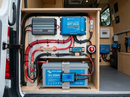
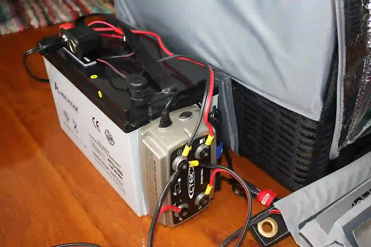
No, you cannot charge LiFePO4 directly from alternator circuits without a dedicated current-limiting DC-to-DC charger. Because LiFePO4 internal resistance is virtually zero (≤ 0.5 mΩ), the battery bank demands maximum output continuously. At low engine idle, reduced rotor fan cooling causes alternator stator temperatures to exceed 150°C, melting insulation, while sudden BMS disconnects generate destructive 100V load-dump spikes.
⚙ Engineering Scope & Operating Boundaries:
- Tested Alternator Topology: 12V 120A to 250A OEM internal-fan claw-pole (Lundell) automotive alternators.
- Lithium Chemistry: 12.8V Lithium Iron Phosphate (LiFePO4) prismatic/cylindrical cells with ultra-low internal resistance (≤ 0.5 mΩ).
- Stator Continuous Thermal Threshold: Maximum 105°C (221°F) casing limit before Class F enamel insulation degradation.
- Continuous Idle Derating Margin: Fixed 50% nameplate derate at engine idle (≤ 800 RPM) to account for reduced rotor cooling fan airflow.
- Electrical Code Governance: ABYC Standard E-11 (AC & DC Systems on Boats), SAE J1113-11 (Automotive Transients), and NEC Article 706.
⚙ Engineering Scope & Operating Boundaries:
- Tested Alternator Topology: 12V 120A to 250A OEM internal-fan claw-pole (Lundell) automotive alternators.
- Lithium Chemistry: 12.8V Lithium Iron Phosphate (LiFePO4) prismatic/cylindrical cells with ultra-low internal resistance (≤ 0.5 mΩ).
- Stator Continuous Thermal Threshold: Maximum 105°C (221°F) casing limit before Class F enamel insulation degradation.
- Continuous Idle Derating Margin: Fixed 50% nameplate derate at engine idle (≤ 800 RPM) to account for reduced rotor cooling fan airflow.
- Electrical Code Governance: ABYC Standard E-11 (AC & DC Systems on Boats), SAE J1113-11 (Automotive Transients), and NEC Article 706.
- Why You Cannot Charge LiFePO4 Directly from an Alternator
- The Stator Thermal Burnout Physics at Engine Idle
- The 50% Continuous Idle Derating Formula
- Interactive Alternator Thermal & DC-DC Sizing Calculator
- Verified DC-DC Charging & Auxiliary Lithium Hardware Kit
- The Three Engineered Solutions for Safe Alternator Charging
- Conductor Sizing, Fusing & Voltage Drop Standards (ABYC E-11 & NEC 705)
- 6-Step Field Installation & Verification Protocol
- Key Takeaways & Core Engineering Rules
- Frequently Asked Questions (FAQ)
This guide examines the electromagnetic and thermal physics governing alternator-to-lithium charging, details the 50% continuous idle derating formula, and provides verified installation blueprints for DC-to-DC converters and temperature-regulated dual-alternator setups.
Why You Cannot Charge LiFePO4 Directly from an Alternator
To understand why direct alternator charging destroys vehicle electrical components, one must examine how original equipment manufacturer (OEM) alternators regulate power compared to dedicated multi-stage chargers. An alternator contains an internal diode rectifier and a basic pulse-width-modulated (PWM) voltage regulator set between 13.8V and 14.2V DC. It does not monitor output current; it only detects system voltage.
When charging a standard flooded lead-acid or AGM starter battery, the battery’s internal chemical resistance (typically 10 to 25 milliohms) increases rapidly as State of Charge (SOC) rises. By Ohm’s law (I = ΔV / R), this rising internal resistance automatically throttles the acceptance current down from 50A to under 10A within 15 to 20 minutes of engine operation, allowing the alternator to cool down.
In contrast, lithium iron phosphate (LiFePO4) chemistry exhibits an exceptionally low internal impedance—typically under 0.5 milliohms per cell string. Consequently, a discharged LiFePO4 battery behaves almost as an electrical dead short to a 14V alternator, continuously demanding every ampere of current the alternator stator can physically produce until the battery reaches roughly 95% to 98% SOC.
The Stator Thermal Burnout Physics at Engine Idle
The primary mechanical failure mode of an alternator wired directly to lithium batteries is thermal winding insulation breakdown. Automotive alternators rely on internal centrifugal fans attached directly to the rotor shaft. The volume of cooling airflow forced across the stator coils is directly proportional to rotational speed.
Manufacturers calibrate alternator nameplate ratings (e.g., 140A) at a standardized bench speed of 6,000 alternator shaft RPM, which corresponds to approximately 1,800 to 2,000 engine RPM under cruising highway conditions. However, when an off-grid vehicle is idling at a traffic signal, navigating city congestion, or parked with the engine running to recharge batteries, the engine spins at only 650 to 750 RPM (roughly 1,800 to 2,200 alternator RPM).
At these idle speeds, cooling airflow drops by approximately 70%. Meanwhile, Joulean resistive heating in the copper stator windings follows the square of the current:
Ploss = I2 × Rstator
Where Rstator is the copper winding resistance (roughly 0.05 ohms when hot). Under a normal lead-acid idle load of 35A (vehicle headlights, engine management, and minimal battery taper), the thermal dissipation inside the casing is:
Ploss = (35A)2 × 0.05 Ω = 61.25 Watts
However, when a 200Ah LiFePO4 bank is connected directly via a mechanical solenoid, the total current draw surges to the alternator’s maximum output limit—roughly 120A at idle:
Ploss = (120A)2 × 0.05 Ω = 720.0 Watts
This represents an 11.7-fold increase in internal thermal energy generation inside an enclosed engine bay with 70% reduced convective airflow. As documented in technical research by Victron Energy in Wiring Unlimited and empirical bench testing from Sandia National Laboratories (SAND2013-5131 / OSTI ID 808812), alternator stator temperatures escalate past 150°C (302°F) within 10 to 15 minutes of continuous idle charging. Above 155°C, the enamel insulation coating on the stator copper breaks down, causing turn-to-turn dead shorts, smoke, and catastrophic rectifier diode failure.

⚠ CRITICAL SAFETY HAZARD: High-Voltage Inductive Alternator Load-Dump (ISO 7637-2)
The Failure Mechanism: When a LiFePO4 battery approaches 100% state of charge, its internal Battery Management System (BMS) continuously monitors individual cell voltages. If a single cell exceeds the overvoltage protection threshold (typically 3.65V), the internal solid-state MOSFET switches trip open in less than 2 milliseconds.
The Electrical Consequence: Because the alternator rotor contains a heavily energized magnetic field with significant inductance (L ≈ 0.05 H), disconnecting an 80A to 120A charging current instantaneously produces a massive inductive kick (V = −L × di/dt). According to ISO 7637-2 Test Pulse 5a standards, this unfiltered transient generates an inductive overvoltage spike between 80V and 120V DC lasting up to 400 milliseconds.
The Disaster: Standard 12V automotive electronics are rated for transient voltages of only 24V to 36V. A 100V load-dump spike instantly punches through silicon junctions, permanently frying the vehicle Engine Control Unit (ECU), digital instrument clusters, ABS modules, and alternator diode bridges.
The 50% Continuous Idle Derating Formula
To prevent stator burnout on vehicles utilizing alternator power for auxiliary energy storage, electrical engineers enforce a standardized continuous idle derating limit:
Iidle_safe = Irated × 0.50
Where Irated is the manufacturer nameplate cold rating stamped on the alternator housing. From this thermal budget, the vehicle’s essential base chassis loads must be deducted to calculate available net auxiliary charging capacity:
Inet_aux_available = (Irated × 0.50) − Ichassis_base
For example, in a modern conversion van with a 150A OEM alternator and a baseline chassis load of 35A (ignition, radiator fans, daytime running lights):
Inet_aux_available = (150A × 0.50) − 35A = 75A − 35A = 40A DC
Under this calculation, installing a 30A or 40A current-limiting DC-to-DC charger guarantees that total idle alternator output remains under 75A, preventing thermal runaway in stop-and-go traffic.
Direct Amazon Associates Selection
To prevent alternator stator thermal burnout, eliminate inductive BMS load-dump spikes, and maintain low-resistance voltage delivery, mobile off-grid electrical systems require dedicated current-limiting converters, high-capacity auxiliary storage, and ABYC-compliant pure copper cabling:
Renogy 12V 40A On-Board DC-to-DC Battery Charger
The definitive current-limiting barrier between vehicle alternator and LiFePO4 bank. Enforces a strict 40A ceiling, delivers multi-stage smart charging curves, isolates starting batteries, and features D+ smart ignition sensing for modern Euro 5/6 alternators.
Super Empower 12.8V 100Ah LiFePO4 Deep Cycle Battery
Premium Grade-A prismatic lithium cells delivering 1,280Wh of deep-cycle capacity. Built-in 100A continuous BMS with integrated low-temperature charge cutoff protection, zero memory effect, and seamless compatibility with 40A DC-DC charging profiles.
VTOMAN 110W Portable Foldable Solar Panel
High-conversion monocrystalline folding solar array. Keeps house LiFePO4 batteries continuously topped off while parked at camp with the engine shut off, eliminating unnecessary engine idling and reducing alternator duty cycles.
WindyNation 4 AWG Pure Copper Battery Cable Pair with ANL Fuse
Ultra-flexible fine-strand 100% pure oxygen-free copper conductors engineered for mobile battery runs. Minimizes DC line resistance and voltage drop (< 2%) while the integrated 60A/80A ANL fuse holder protects vehicle chassis wiring from catastrophic dead shorts.
Amazon Associates Affiliate Disclosure: As an Amazon Associate, this site earns qualifying purchases from qualifying links at zero additional cost to you. Hardware selections are independently evaluated against ABYC E-11 and SAE J1113 electrical engineering standards.
Amazon Associates Affiliate Disclosure: As an Amazon Associate, this site earns qualifying purchases from qualifying links at zero additional cost to you. Hardware selections are independently evaluated against ABYC E-11 and SAE J1113 electrical engineering standards.