To size off-grid solar wires correctly, calculate both voltage drop and thermal ampacity. Target a maximum voltage drop of 2% for battery-to-inverter runs and 3% for array home runs using CM = (2 × K × I × L) / Vdrop. Ensure conductor ampacity exceeds 1.25 × I continuous duty per NEC 690.8.
Across off-grid electrical forums and warranty service logs, a frequent assumption among beginner builders is that severe conductor overheating is primarily a high-voltage phenomenon. In direct-current physics, the reality is precisely the opposite: low-voltage systems require dramatically higher current to deliver identical wattage (I = P / V). A 12-volt inverter delivering 1,500 watts draws a continuous 125 amperes through its battery cables, whereas a 48-volt setup draws just 31 amperes. When cables are selected without verifying circular mil cross-sectional area and thermal ampacity, conductor resistance (I2R) converts scarce stored energy into intense heat, induces inverter undervoltage faults, and creates severe insulation fire risks.
National Electrical Code (NEC) guidelines establish clear boundaries to mitigate these hazards: Article 690.8 mandates a 125% continuous duty multiplier on maximum photovoltaic current, while standard off-grid engineering limits circuit voltage drop to 2% on critical battery lines and 3% on PV array home runs. Using an engineering-calibrated solar wire size calculator allows DIY designers to determine the exact American Wire Gauge (AWG) or kcmil conductor size required to balance allowable voltage drop against thermal ampacity limits, ensuring maximum generated watt-hours reach your battery bank safely.
⚡ Interactive Wire, String & Battery Sizing Tools
Live Simulation
Designing an off-grid array or battery bank? Test wire runs, temperature-adjusted string voltages, and high-current fuses with our specialized tools:
Interactive Off-Grid Solar Wire Size & Voltage Drop Calculator
Input your system DC voltage, current load, and one-way distance to calculate the code-compliant conductor gauge, exact voltage drop, power lost as heat, and minimum overcurrent protection device (OCPD) rating.
The Physics of DC Resistance: Ohm’s Law and Circular Mils
To understand why wire sizing is so critical in direct current circuits, one must examine the physical properties of metallic conductors. Unlike alternating current (AC) grid power, which operates at elevated transmission voltages (120V to 240V in households and thousands of volts on utility poles) to minimize current flow, off-grid battery systems frequently operate at low nominal voltages such as 12V, 24V, or 48V DC. Because electrical power equals voltage multiplied by current (P = V × I), moving 2,400 Watts of power requires 10 Amperes at 240V AC, but demands an immense 200 Amperes at 12V DC.
Every electrical conductor possesses an inherent internal resistance (R) determined by its cross-sectional area, its physical length, and the resistivity of its metallurgical composition. According to Ohm’s Law (V = I × R), when current (I) passes through this resistive pathway, a proportional portion of the electrical potential drops along the length of the wire before reaching the intended load. The standard equation used by engineers and our solar wire size calculator to determine the required conductor cross-sectional area in circular mils (CM) is expressed as:
2 × K × I × L
Vdrop
Where the individual variables are defined as follows:
- 2: Multiplier accounting for the complete round-trip loop of the circuit (the positive conductor carrying current to the equipment, and the negative conductor returning current back to the source).
- K: The specific resistivity constant of the conductor material at standard operating temperature (approximately 75°C). For annealed copper, K = 12.9 Ω·cmil/ft. For aluminum conductors, K = 21.2 Ω·cmil/ft.
- I: The maximum operational design current in Amperes DC.
- L: The one-way physical length of the cable run in feet.
- Vdrop: The maximum allowable voltage drop expressed in Volts, calculated by multiplying the system operating voltage by the desired percentage threshold (e.g., 24V × 0.02 = 0.48V).
A circular mil is an engineering unit of area equal to the area of a circle with a diameter of one mil (one thousandth of an inch, or 0.001 inch). By calculating the required circular mils and cross-referencing standard American Wire Gauge tables, installers ensure that the conductor cross-section is sufficiently large to keep resistive voltage drop below the system design threshold.
The Dual-Threshold Rule: Voltage Drop vs. Thermal Ampacity in Our Solar Wire Size Calculator
A frequent mistake encountered in DIY off-grid installations is relying exclusively on a basic ampacity chart to select wire size. While ampacity dictates the maximum current a wire can carry before its insulation overheats and melts, it completely ignores physical distance. Sizing a solar cable requires satisfying two distinct, mandatory criteria:
- Thermal Ampacity Threshold (NEC 690.8 & 310.16): The physical conductor must have sufficient cross-sectional copper mass to conduct continuous maximum current without exceeding its insulation temperature rating (typically 75°C or 90°C). Under NEC Article 690.8(B), solar photovoltaic circuits are considered continuous duties and must carry a safety multiplier of 125% (1.25 × I) before selecting conductor ampacity.
- Voltage Drop Efficiency Threshold (NEC 210.19 Informational Note): The total circuit resistance across the physical distance must not restrict voltage by more than 2% to 3%. In low-voltage systems, a cable run of just 15 to 20 feet can easily drop 5% to 8% of the system voltage even when operating well within its thermal ampacity rating.
The Engineering Reality: Distance Determines the Winner
On extremely short wire runs (such as a 3-foot cable between a 48V battery busbar and an inverter), thermal ampacity almost always governs wire selection. Conversely, on long wire runs (such as a 70-foot home run from an exterior solar array down to a basement MPPT charge controller), voltage drop dictates wire selection. A wire that is thermally safe can still cause catastrophic system underperformance due to voltage drop.
Master AWG Reference Table for DC Solar Installations
The following technical reference table compiles physical conductor characteristics, circular mil areas, direct current electrical resistance at 75°C, and code-rated ampacities per National Electrical Code (NEC) Chapter 9 Table 8 and Table 310.16. Use this table alongside our solar wire size calculator to verify conductor specifications during system planning.
| Conductor Size (AWG / kcmil) | Cross-Section Area (mm2) | Area (Circular Mils) | DC Resistance (Ω / 1,000 ft @ 75°C) | Copper Ampacity (75°C THHN/RHW) | Copper Ampacity (90°C PV Wire) | Typical Off-Grid Circuit Application |
|---|---|---|---|---|---|---|
| 14 AWG | 2.08 | 4,110 | 3.070 | 20 A | 25 A | Small LED lighting circuits, sensor wiring, low-power instrumentation |
| 12 AWG | 3.31 | 6,530 | 1.930 | 25 A | 30 A | Single 100W-200W panel branch runs, 12V auxiliary DC outlets |
| 10 AWG | 5.26 | 10,380 | 1.210 | 35 A | 40 A | Standard commercial PV module leads, string home runs up to 30A |
| 8 AWG | 8.37 | 16,510 | 0.764 | 50 A | 55 A | Parallel string combiner box outputs, small 30A MPPT battery leads |
| 6 AWG | 13.30 | 26,240 | 0.491 | 65 A | 75 A | Medium MPPT charge controller output (40A-60A), DC generator leads |
| 4 AWG | 21.15 | 41,740 | 0.308 | 85 A | 95 A | Heavy 60A-80A MPPT battery leads, 1,000W 12V / 2,000W 24V inverters |
| 2 AWG | 33.62 | 66,360 | 0.194 | 115 A | 130 A | 100A charge controllers, 1,500W 12V inverters, 3,000W 24V inverters |
| 1/0 AWG | 53.49 | 105,600 | 0.122 | 150 A | 170 A | 2,000W 12V inverters, 4,000W 24V inverters, 48V battery interconnects |
| 2/0 AWG | 67.43 | 133,100 | 0.0967 | 175 A | 195 A | 2,500W-3,000W 12V inverters, main battery bank parallel bridging links |
| 4/0 AWG | 107.20 | 211,600 | 0.0608 | 230 A | 260 A | Heavy 3,000W+ 12V / 6,000W 24V / 12,000W 48V main inverter power feeds |
| 250 kcmil | 126.70 | 250,000 | 0.0515 | 255 A | 290 A | Commercial split-phase off-grid power centers, industrial battery banks |
Conductor Insulation Ratings: PV Wire vs. USE-2 vs. THHN vs. Marine-Grade Copper
The metallurgical cross-section of a wire only represents half of the engineering equation; the outer insulation jacket determines where and how the cable can be safely deployed. In solar power installations, outdoor environmental factors—such as ultraviolet sunlight, extreme thermal swings, ozone exposure, and mechanical abrasion—will rapidly degrade standard building wire.
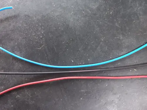
Understanding the distinctions between common cable types ensures electrical code compliance and prevents premature wiring failure:
1. Photovoltaic Wire (UL 4703 PV Wire)
Photovoltaic Wire (PV Wire) is the premier standard for outdoor solar module interconnection. Engineered with thick, cross-linked polyethylene (XLPE) or thermoset insulation, PV wire is rated for 600V, 1,000V, or 2,000V DC. It is sunlight-resistant, flame-retardant, and certified for wet, sub-zero (-40°C), and high-heat (+90°C or +105°C) outdoor environments. Crucially, NEC Article 690 specifically mandates PV Wire for exposed, ungrounded DC solar array wiring where double-insulation protection is required.
2. USE-2 Cable (Underground Service Entrance)
Historically common in early solar installations, USE-2 cable features a thermoset jacket suitable for direct burial and outdoor weather exposure. However, USE-2 is generally rated only to 600V DC and is restricted under modern electrical codes to grounded solar arrays. It lacks the dual-insulation and crush-resistance standards of modern UL 4703 PV wire and cannot be installed on ungrounded transformerless inverter strings.
3. THHN / THWN-2 Building Wire
Thermoplastic High Heat-resistant Nylon-coated (THHN) wire is the standard conductor used in residential AC conduit. While dual-rated THWN-2 is water-resistant and rated for 90°C wet environments, thermoplastic insulation breaks down quickly under direct ultraviolet sunlight. THWN-2 must never be installed exposed on an outdoor solar array. It is strictly approved for routing inside raceways, metallic conduit (EMT), or PVC conduit once the solar array circuits transition beneath the roof deck or into a combiner box.
4. Marine-Grade Tinned Copper Battery Cable (Class K / SAE J1127)
For high-amperage battery banks and inverter connections, standard stiff building wire (Class B stranding with 7 or 19 rigid strands) is unsafe. High current passing through rigid wire transmits mechanical vibration into battery terminals, eventually working terminal bolts loose and creating severe electrical arcing hazards. True battery cables utilize Class K or Class M fine-stranded copper (containing hundreds or thousands of hair-thin strands) coated with electroplated tin. Tinned copper prevents atmospheric corrosion and oxidation, while ultra-fine stranding ensures maximum contact surface area within heavy-duty crimp lugs.
Environmental Derating: Ambient Temperature, Roof Proximity and Conduit Fill
Conductor ampacity ratings published in standard tables assume an ambient air temperature of 30°C (86°F) and no more than three current-carrying conductors grouped together in a single conduit. When installing solar wiring on outdoor rooftops or inside engine compartments, real-world temperatures far exceed standard test bench benchmarks.
According to NEC Table 310.15(B)(1) and 310.15(B)(2), designers must apply two reduction multipliers to calculate a conductor’s true safe ampacity (Isafe):
Where these environmental correction factors represent:
- Temperature Correction Factor (Ftemp): Photovoltaic modules absorb radiant solar energy, frequently elevating conduit temperatures mounted close to roof shingles to 50°C–60°C (122°F–140°F). For a 90°C rated conductor operating in 55°C ambient air, the temperature correction factor is 0.76. A 10 AWG wire rated for 40 Amperes is derated to just 40 × 0.76 = 30.4 Amperes.
- Conduit Fill Adjustment Factor (Ffill): When multiple circuit conductors are pulled through a shared conduit or raceway, heat dissipation is restricted. If 4 to 6 current-carrying conductors share a conduit, NEC mandates an adjustment factor of 0.80. If 7 to 9 conductors share the conduit, the factor drops to 0.70.
Failure to apply thermal derating during the initial planning phase can lead to silent cable insulation degradation, where conductors operating well beneath their nominal room-temperature limit slowly char and harden inside hot rooftop conduits.
MC4 Connectors, Terminal Lugs and Crimping Integrity
A precision-sized copper conductor is only as dependable as the terminations that anchor its ends. In high-amperage DC solar installations, improper crimps and mismatched connectors represent the single most common origin of thermal hotspots, localized resistance, and catastrophic series arc fires.
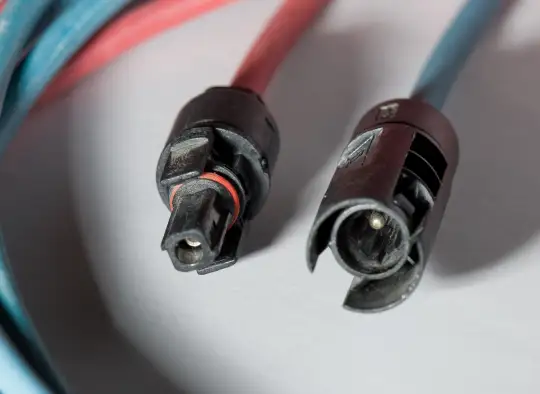
When assembling DC interconnections, follow these critical wiring standards:
- Never Cross-Mate Connector Brands: While many third-party connectors are marketed as “MC4 compatible,” microscopic dimensional variances between manufacturers cause loose pin contact pressure. Loose electrical contact under 15A–30A of continuous direct current generates immense contact resistance, melting the polycarbonate housing and igniting surrounding roofing materials. Always mate identical brand connectors (such as genuine Stäubli MC4 with Stäubli MC4).
- Use Ratcheting Calibrated Crimp Tools: Never crimp MC4 pins or battery terminal lugs with standard pliers, vise-grips, or hammer-indent punches. Standard pliers crush the brass pin unevenly, leaving internal air pockets that corrode and overheat. Professional ratcheting crimp tools deliver complete cold-weld compression, fusing the fine copper strands into a solid gas-tight copper mass.
- Dual-Wall Adhesive Heat Shrink: On high-current battery cable lugs (4 AWG through 4/0 AWG), always seal the joint between the cable insulation and the copper lug barrel using dual-wall polyolefin heat shrink tubing with internal hot-melt adhesive. The adhesive flows into the cable end, creating an airtight moisture barrier that prevents sulfuric acid vapors and ambient humidity from wicking into the copper stranding.
Hazards of Undersized Wiring: Voltage Sag, Heat Loss and Inverter Trips
What happens when an off-grid solar installation uses undersized wiring? Many builders mistakenly believe that undersized wire simply means losing a fraction of solar wattage. In reality, the operational consequences in an off-grid power plant are far more disruptive and dangerous.

1. Nuisance Inverter Low-Voltage Cutoffs
The most common symptom of undersized battery-to-inverter cables is premature inverter shutdown. When a heavy inductive appliance—such as a deep well pump, refrigerator compressor, or power saw—starts up, the inverter draws a massive surge current lasting a few hundred milliseconds. If the DC cables between the battery and the inverter have excessive resistance, the surge current causes an instant, sharp voltage sag (Vsag = Isurge × Rcable).
Even if a lithium iron phosphate battery bank is sitting comfortably at 80% state-of-charge (e.g., 26.4V on a 24V system), a 2.5V drop across undersized 4 AWG cables instantly pulls the inverter DC input voltage below its 21.0V low-voltage disconnect cutoff threshold. The inverter sounds a low-battery fault alarm and trips offline, despite the battery bank holding abundant stored energy.
2. False MPPT Charge Controller Tracking
When undersized wires connect a solar array to an MPPT charge controller, the resistance of the cable dynamically alters the voltage observed by the controller’s tracking algorithm. Under fluctuating cloud cover, the controller struggles to pinpoint the true maximum power point of the photovoltaic array, resulting in suboptimal energy harvesting and prolonged battery bulk-charging cycles.
3. Cumulative Battery Energy Theft
Electrical resistance dissipates power as thermal energy (P = I2 × R). In a 12V system pushing 80 Amperes through an undersized 6 AWG cable run with 0.05 Ohms of loop resistance, the power lost as pure heat is 802 × 0.05 = 320 Watts. Over four peak charging hours, more than 1.28 kilowatt-hours of precious battery energy is lost heating up the wires inside your walls instead of charging your storage cells.
Three Real-World Field Sizing Scenarios
To demonstrate the practical application of our solar wire size calculator and the governing balance between thermal ampacity and voltage drop, review these three realistic field calculations from off-grid builds.
Scenario 1: High-Voltage Rooftop Array to MPPT Controller (Long Run)
System Parameters: A 1,600-Watt solar array wired in a series string of four 400W commercial panels (Vmp = 124V, Imp = 12.9A, Isc = 13.8A). One-way distance from roof to basement charge controller: 65 feet.
- Thermal Ampacity Check: Continuous current design requires 1.25 × Isc = 1.25 × 13.8 = 17.25 Amperes. Standard 12 AWG copper wire carries 25A–30A and easily satisfies thermal safety.
- Voltage Drop Evaluation: Target maximum drop is 3% of 124V (3.72V). Required circular mils:
CM = (2 × 12.9 × 12.9A × 65ft) / 3.72V = 21,631 / 3.72 = 5,815 Circular Mils
- Conductor Selection: When verifying this circuit in our solar wire size calculator, 12 AWG provides 6,530 CM (resulting in a 2.67% drop), while 10 AWG provides 10,380 CM (resulting in an ultra-clean 1.68% drop, or just 2.08V). Selection: 10 AWG UL 4703 PV Wire provides superior margin and low resistance.
Scenario 2: 60A MPPT Charge Controller to 24V LiFePO4 Battery (Short Run)
System Parameters: A 60-Amp MPPT charge controller bulk-charging a 24V lithium battery bank at maximum continuous current. One-way distance: 8 feet.
- Thermal Ampacity Check: Continuous output requires 60A × 1.25 = 75 Amperes minimum rating. Per NEC Table 310.16, 6 AWG copper (75°C rating = 65A) is insufficient. A minimum of 4 AWG copper (rated 85A at 75°C) is required by code.
- Voltage Drop Evaluation: Target maximum drop is 2% of 24V (0.48V). Required circular mils:
CM = (2 × 12.9 × 60A × 8ft) / 0.48V = 12,384 / 0.48 = 25,800 Circular Mils
- Conductor Selection: Testing this circuit in our solar wire size calculator reveals that 6 AWG provides 26,240 CM (satisfying voltage drop at 1.96%), but fails the mandatory 75A thermal ampacity threshold! Selection: 4 AWG fine-stranded copper (41,740 CM) must be installed, keeping voltage drop down to 1.23% (0.30V) while satisfying code safety.
Scenario 3: 3,000W Pure Sine Wave Inverter to 12V Battery Bank (Extreme Amps)
System Parameters: A 3,000W continuous inverter running at full load from a 12V LiFePO4 battery bank. Assuming a typical 90% inverter efficiency, full continuous current draw is (3,000W / 0.90) / 12V = 277.8 Amperes. One-way cable distance: 5 feet.
- Thermal Ampacity Check: Continuous load design (277.8A × 1.25 = 347.25A) requires massive conductors. Even standard 4/0 AWG copper is rated for 230A–260A. An installation of this magnitude requires either dual parallel runs of 2/0 AWG (rated 175A × 2 = 350A) or an ultra-heavy 350 kcmil conductor with a Class T fuse.
- Voltage Drop Evaluation: In a 12V system, 2% drop is merely 0.24 Volts! Any wire smaller than 4/0 AWG will cause the inverter to fault during refrigerator motor starting surges.
- Selection: Dual parallel runs of 2/0 AWG or a single 4/0 AWG welding cable run under 4 feet with a 350A Class T fuse. (Better yet: this scenario clearly illustrates why 3,000W systems should be designed around 24V or 48V to cut current in half or quarter!).
Step-by-Step Installation & Verification Protocol
Once you have calculated the required wire size with our solar wire size calculator, implement these field installation best practices to ensure longevity and fire safety:
- Mechanical Cable Pulling and Bend Radius: Never bend thick DC solar or battery cables sharper than the manufacturer’s minimum bend radius (typically 4 to 8 times the overall cable outer diameter). Kinking thick copper strands fractures the metal conductors internally and creates localized high-resistance bottlenecks.
- Calibrated Torque Wrench Application: Over 70% of electrical connection failures stem from improper terminal tightness. Under-tightened lugs wiggle loose under thermal expansion; over-tightened lugs strip threads and distort terminal flats. Always use an insulated torque screwdriver or wrench matching the manufacturer’s torque specification (commonly 45 to 55 inch-pounds for breaker terminals and 80 to 120 inch-pounds for M8/M10 battery studs).
- Strain Relief and UV Support: Exterior rooftop PV wire must be supported every 4.5 feet and within 12 inches of every junction box using stainless steel solar cable clips. Never use standard nylon zip ties on exterior arrays; sunlight breaks down standard nylon in less than 18 months, causing cables to sag against rough roof shingles and chafe through their insulation.
- Full-Load Multimeter Verification: After commissioning, verify your theoretical calculations under real-world conditions. Wait until midday when the solar array or inverter is operating at peak current. Set a digital multimeter to millivolts DC, place one probe on the source terminal and the other probe on the load terminal of the positive cable, and measure the live voltage drop across the wire. If the measured drop exceeds your design target, inspect every crimp and terminal lug for high contact resistance.
Frequently Asked Questions (FAQ)
1. Why does high voltage allow smaller wire sizes in solar arrays?
Electrical power is the product of voltage and current (P = V × I). When you increase voltage by wiring solar panels in series, the amperage required to carry the exact same wattage drops proportionally. Because electrical resistance and heat dissipation are driven by the square of the amperage (I2 × R), cutting current in half reduces power losses by a factor of four. This allows a 120V PV array to transmit power across 80 feet using thin 10 AWG wire with less than 2% loss, whereas transmitting the same wattage at 24V would require a thick 2 AWG cable.
2. Can I use standard Romex or NM-B cable for my solar wiring?
No. Non-Metallic Sheathed Cable (Romex / NM-B) is strictly prohibited in outdoor, wet, damp, or photovoltaic DC environments. Romex is rated only for interior dry walls, features thin 60°C/90°C PVC insulation that degrades rapidly in sunlight, and lacks the voltage rating and moisture barrier required for solar arrays. Using Romex outdoors will void equipment warranties, fail electrical inspections, and create severe electrical shock and fire hazards.
3. What is the maximum acceptable voltage drop for off-grid battery cables?
The industry standard for critical battery-to-inverter and battery-to-charge controller cables is a maximum voltage drop of 2.0%, with 1.5% considered best practice for high-surge 12V systems. In our solar wire size calculator, keeping voltage drop beneath 2% ensures that sensitive inverter low-voltage cutout circuits do not trip prematurely during heavy inductive appliance start-ups.
4. Is copper wire always better than aluminum for solar installations?
For residential off-grid systems, battery banks, and rooftop solar arrays, annealed copper is universally preferred. Copper has roughly 60% higher electrical conductivity than aluminum (K = 12.9 vs. 21.2), allowing for significantly thinner conductors and smaller conduit sizes. Additionally, copper is not prone to galvanic oxidation and thermal creep, which can loosen aluminum connections over time. Aluminum is primarily utilized in large utility-scale commercial ground arrays where the lower raw material cost of heavy aluminum feeder conductors offsets the requirement for larger conduit.
5. How does wire temperature affect solar system voltage drop?
As metallic conductors heat up under direct sunlight and high electrical loads, the vibrating metal atoms impede the flow of electrons, causing electrical resistance to increase. The resistance of copper wire increases by approximately 0.393% for every degree Celsius above standard room temperature (20°C). A conduit exposed on an asphalt shingle roof operating at 60°C (140°F) experiences roughly 15% higher internal resistance than the same wire operating in a cool basement, increasing voltage drop and waste heat.