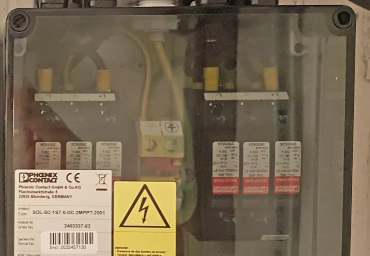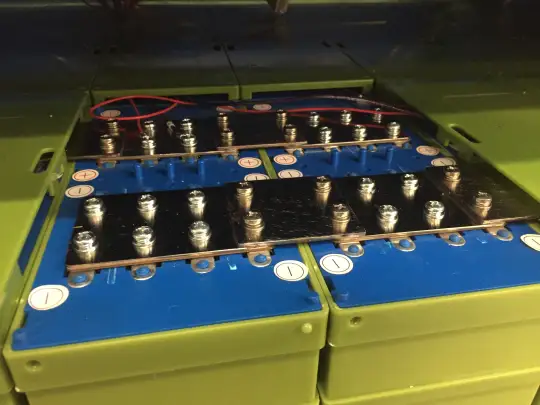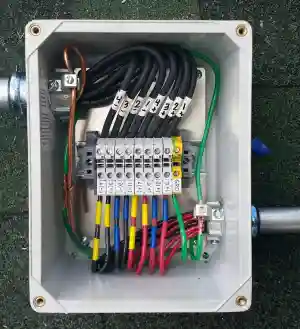
In an off-grid solar power system, selecting overcurrent protection is frequently approached with dangerous oversimplification. Builders often treat direct-current (DC) miniature circuit breakers (MCBs) as interchangeable drop-in equivalents to household alternating-current (AC) panel breakers, or purchase inexpensive unbranded DIN-rail breakers online without understanding arc-quenching physics. This fundamental misunderstanding causes blown enclosures, welded breaker contacts, and catastrophic electrical fires in DIY solar power centers.
Direct current behaves fundamentally differently from alternating current when interrupted under electrical load. While 60 Hz alternating current naturally reverses direction and passes through zero volts 120 times every second—allowing electrical arcs to self-extinguish as contacts separate—direct current maintains a continuous, uninterrupted electromotive potential. Opening a DC circuit under load generates a sustained, superheated plasma arc reaching temperatures above 3,000°C (5,432°F). Extinguishing this plasma requires specialized magnetic blowout coils, de-ionizing splitter plates, and strict adherence to directional polarity rules.
To size a solar DC circuit breaker correctly, apply a continuous duty multiplier to the maximum prospective circuit current based on circuit location, and verify that both the DC voltage rating and Ampere Interrupting Capacity (AIC) exceed system fault levels:
- PV String Circuits (NEC 690.8 & 690.9): Breaker Rating ≥ Isc × 1.25 × 1.25 = 1.56 × Isc. Voltage rating must exceed cold-weather open-circuit voltage (Voc(cold)) per NEC 690.7.
- Charge Controller Output & DC Branch Circuits: Breaker Rating ≥ Maximum Continuous Current × 1.25 (the 125% continuous duty rule under NEC 210.20).
- Inverter Battery Feeds: Breaker Rating ≥ [Inverter Rated Continuous Power ÷ (Low Battery Cutoff Voltage × Inverter Efficiency)] × 1.25.
- The Polarity Safety Standard: Never install polarized DC breakers on bidirectional circuits (such as cables between a battery bank and an inverter-charger). Reverse current flow reverses the magnetic blowout force, driving the plasma arc into the plastic housing instead of the arc chute, resulting in explosive breaker failure. Bidirectional lines require UL 489B-listed non-polarized DC breakers or catastrophic-duty Class T fuses.
1. The Physics of DC Arc Interruption: Why DC Breakers Are Unique
To safely design overcurrent protection for an off-grid installation, one must understand how circuit breakers interrupt electrical faults. When high current flows through a circuit breaker, an internal bimetallic strip heats and flexes (thermal protection against sustained overloads), or a magnetic solenoid pulls a trip armature (magnetic protection against instantaneous dead shorts). The physical mechanical contacts snap open.
In a 120V or 240V AC circuit, the sinusoidal voltage wave passes through zero volts 120 times every second (at 60 Hz). When the contacts separate, the plasma arc cools and naturally de-ionizes at the zero-crossing moment, allowing dielectric air to fill the gap and permanently stop current flow. Standard AC breakers rely entirely on this natural cyclic zero-crossing.
Direct-current sources—including photovoltaic solar strings, MPPT charge controllers, and battery banks—do not cycle. When breaker contacts open in a 48V, 150V, or 500V DC circuit, the air between the separating contacts ionizes into a conductive plasma column. Because there is no zero-crossing voltage collapse, current continues to bridge the physical air gap. If the breaker lacks specialized arc-extinguishing components, the plasma arc burns continuously, melting terminal blocks, liquefying the copper busbars, and igniting surrounding timber or plastic enclosures.
| Electrical Parameter | Alternating Current (AC) Breaker | Direct Current (DC) Breaker |
|---|---|---|
| Arc Extinction Mechanism | Natural AC sine-wave zero crossing (120x per second at 60 Hz). | Magnetic blowout coils/magnets driving arc into de-ionizing splitter plates. |
| Contact Gap Geometry | Narrow contact separation gap (typically 1.5 mm to 3 mm). | Wide mechanical contact travel and elongated arc-chute geometry. |
| Polarity Sensitivity | Non-directional (current alternates back and forth). | Can be polarized (+/-) or non-polarized depending on magnet orientation. |
| DC Voltage Rating on AC Breaker | Usually 0V DC, or strictly de-rated to ≤ 32V–48V DC maximum. | Engineered for 60V, 150V, 300V, 600V, or 1,000V DC continuous potential. |
| Failure Mode Under DC Fault | Contacts weld shut; plasma arc burns through plastic casing. | Safely stretches, cools, and quenches arc inside arc chute. |
2. Polarized vs. Non-Polarized DC Breakers: The Reverse-Feeding Trap
One of the most dangerous hazards in off-grid solar wiring is the misuse of polarized DC miniature circuit breakers. To extinguish high-voltage DC arcs economically, many manufacturers embed a small permanent neodymium magnet adjacent to the electrical contacts.
When DC current flows through the breaker in the designed forward direction, the magnetic field interacts with the moving electrical charges (the Lorentz force, F = q(v × B)). This electromagnetic force pushes the plasma arc laterally away from the contacts and blows it deep into an array of nickel-plated steel arc splitter plates (the de-ionizing arc chute). The plates divide the single large arc into multiple small, low-voltage arcs, cooling the plasma below its ionization threshold and quenching it within milliseconds.
However, if current flows in the reverse direction through a polarized breaker, the direction of the Lorentz force inverts:
- Instead of blowing outward into the arc chute, the magnetic field pulls the 3,000°C plasma arc inward toward the internal mechanical trip latch and the plastic polycarbonate housing.
- The arc remains trapped between the contacts, liquefying the contact assembly and instantly vaporizing internal springs.
- The breaker catches fire, welds into a solid permanent short circuit, or bursts its enclosure, ejecting molten copper into the electrical box.

⚠ High-Current & Reverse-Feeding Safety Hazard (NEC 240.85):
Never install a polarized DC breaker between an off-grid battery bank and a hybrid inverter-charger. When the inverter powers household loads, current flows from battery to inverter. When a backup generator or grid assist charges the battery, current reverses direction. Under reverse fault conditions, a polarized breaker’s internal permanent magnet deflects the 3,000°C DC plasma arc directly onto its plastic casing, causing the breaker to fail to trip, explode, and weld shut into an active arc-flash fire.
Under National Electrical Code (NEC) Article 240.85, circuit breakers marked with line and load designations, or marked with distinct positive (+) and negative (−) terminals, are strictly prohibited from being reverse-fed. This creates critical design rules across different solar subsystems:
| Subsystem Location | Current Flow Direction | Permissible Breaker Type | Engineering Mandate |
|---|---|---|---|
| PV Array to MPPT Input | Unidirectional (Sunlight → MPPT). | Polarized OR Non-Polarized. | If using polarized, PV(+) must connect to (+) terminal; MPPT input to (−) terminal. |
| MPPT Output to Battery Busbar | Unidirectional under normal operation (MPPT → Battery). | Non-Polarized Strongly Preferred. | In a dead short inside the MPPT, battery bank backfeeds the controller. Polarized breakers may fail to clear this backfeed. |
| Battery Bank to Inverter-Charger | Bidirectional (Discharging ←→ Charging). | NON-POLARIZED ONLY (or Class T Fuse). | Polarized breakers are 100% FORBIDDEN. Current flows both ways depending on whether inverter is powering loads or generator/grid is charging battery. |
| DC Distribution Subpanel to DC Loads | Unidirectional (Battery Busbar → 12V/24V Loads). | Polarized OR Non-Polarized. | Standard marine or automotive DC breakers (Blue Sea, Carling) are non-polarized. |
When sourcing equipment, always look for circuit breakers certified under UL 489B (Molded Case Circuit Breakers for Photovoltaic Systems) or UL 489A (Communications and DC Equipment). Premium brands such as MidNite Solar (MNEPV series) and Carling Technologies produce true bi-directional, non-polarized DC circuit breakers designed specifically for off-grid renewable energy systems. You can learn more about isolating power safely in our solar DC disconnect switch sizing specifications.
3. Sizing Mathematical Formulas: NEC 690.8, 690.9 & 125% Rules
Properly sizing a solar DC circuit breaker requires two distinct mathematical evaluations: continuous current capacity and voltage limit verification. Under National Electrical Code requirements, photovoltaic circuits must be sized for worst-case environmental conditions.
Formula A: Photovoltaic Array String Breaker Sizing (NEC 690.8 & 690.9)
Solar panels are current-limited power sources. In full sunlight, a module cannot produce hundreds of amperes; it is capped at its short-circuit current (Isc). However, cold bright winter days, high-elevation ultraviolet reflections, and cloud-edge lensing phenomena frequently cause solar panels to exceed their Standard Test Condition (STC) nameplate ratings for hours at a time.
To prevent nuisance thermal tripping while guaranteeing cable protection, the National Electrical Code mandates two separate 125% multipliers:
- Maximum Circuit Current (NEC 690.8(A)(1)): Imax = Isc × 1.25. (Accounts for continuous enhanced irradiance above 1,000 W/m²).
- Overcurrent Device Sizing (NEC 690.8(B)(1)): Ibreaker ≥ Imax × 1.25. (Accounts for continuous duty operation exceeding 3 hours).
Combining these factors yields the foundational solar overcurrent sizing constant:
For example, if you connect a series string of residential solar panels with a rated Isc of 11.2 Amperes into a solar combiner box string fusing schematic:
Ibreaker ≥ 11.2 A × 1.5625 = 17.5 A. Rounding up to the next standard breaker size gives a 20 Ampere DC circuit breaker.
Formula B: Charge Controller Output Breaker Sizing
An MPPT solar charge controller steps high PV array voltage down to battery charging voltage, multiplying the output charging current. The breaker installed between the MPPT output and the battery busbar must carry the controller’s full rated continuous output current without thermal tripping:
For a standard 60A MPPT charge controller (such as a Victron SmartSolar 150/60 or MidNite Classic 150), the calculation is: 60 A × 1.25 = 75 Amperes. An 80A rated DC circuit breaker is the standard specified size.
Formula C: Inverter DC Battery Feed Breaker Sizing
Sizing the DC breaker between the battery bank and a pure sine wave inverter requires calculating the maximum DC current drawn at the lowest operating battery voltage, adjusted for the inverter’s conversion efficiency:
Ibreaker(Inverter) ≥ Icontinuous(DC) × 1.25
For instance, consider a 3,000 Watt continuous 48V inverter with a 90% full-load efficiency (η = 0.90) and a low-voltage battery cutoff threshold of 44.0V:
Icontinuous = 3,000 W ÷ (44.0 V × 0.90) = 3,000 ÷ 39.6 = 75.76 Amperes.
Applying the 125% continuous buffer: 75.76 A × 1.25 = 94.7 Amperes. A 100A or 125A heavy-duty non-polarized breaker is selected. Always verify your total continuous load current and battery storage profile using our off-grid solar system sizing calculator, and ensure your conductors match this rating using our solar wire size and ampacity calculator.
💡 Engineering Pro-Tip: Thermal Derating on Grouped DIN-Rail MCBs
When installing multiple thermal-magnetic DC circuit breakers side-by-side on a common DIN rail (such as in multi-string PV combiner boxes or multi-circuit DC subpanels), the heat dissipated by adjacent thermal bimetallic elements compounds. Under IEC 60947-2, group thermal derating factors must be applied: multiply rated ampacity by 0.80 for 4 to 6 adjacent breakers, or install half-module DIN rail dummy spacers (9mm air gaps) between high-amperage breakers to maintain airflow and prevent false nuisance tripping in high summer ambient temperatures.
4. The LiFePO4 Short-Circuit Crisis: AIC Ratings & Exploding Breakers
The explosive popularity of lithium iron phosphate (LiFePO4) server-rack batteries and DIY prismatics (such as EVE 280Ah and 304Ah cells) has created an unprecedented electrical safety challenge in residential off-grid installations.
Every circuit breaker carries an Ampere Interrupting Capacity (AIC) rating—also referred to as the short-circuit breaking capacity (Icu or Icn under IEC 60947-2). The AIC represents the maximum instantaneous fault current that the breaker’s contacts and arc chamber can safely extinguish without vaporizing, welding shut, or rupturing its physical housing.
Traditional flooded lead-acid and AGM deep-cycle batteries have relatively high internal chemical resistance (roughly 10 mΩ to 30 mΩ per 12V monobloc). Under a direct bolted short circuit across battery terminals, lead-acid internal resistance acts as a natural brake, capping prospective short-circuit current to roughly 1,500A to 4,000A.
In stark contrast, modern Grade-A LiFePO4 prismatic cells have an internal AC impedance of less than 0.25 mΩ to 0.40 mΩ per cell. In a 48V (16-cell series, 51.2V nominal) 100Ah or 280Ah battery bank:
- Total internal battery resistance: Rinternal ≈ 16 × 0.00035 Ω = 0.0056 Ω (5.6 milliohms).
- Connecting copper cable and busbar resistance: ≈ 0.0020 Ω (2.0 milliohms).
- Total loop impedance under a bolted short: Rloop ≈ 0.0076 Ω.
Applying Ohm’s law (Ifault = V ÷ R):
Ifault = 53.0 V ÷ 0.0076 Ω = 6,973 Amperes.
If two or three lithium batteries are paralleled together on a common busbar, prospective short-circuit current surges to 15,000A to 25,000A within 2 milliseconds!
Most inexpensive miniature DIN-rail DC circuit breakers sold online are rated for an AIC of only 4,500A (4.5 kA) or 6,000A (6 kA). When a bolted short circuit occurs on a multi-battery lithium bank, the available current exceeds the breaker’s physical containment limits. The internal contacts vaporize into a copper plasma cloud that conducts right around the contacts, destroying the enclosure and blowing shrapnel into the electrical cabinet.

To solve this, off-grid engineers implement a two-tier coordinated protection strategy:
- Upstream Catastrophic Protection: Install a genuine Class T fast-acting fuse rated for 20,000A AIC (at 125V DC) or 100,000A AIC (at 300V AC/DC) directly on the positive battery terminal post or main busbar. For full details on fuse selection, consult our Class T vs ANL battery fuse sizing guide.
- Downstream Operational Disconnect: Use listed heavy-duty DC circuit breakers (such as Blue Sea 187/285 series or MidNite Solar panel breakers) for routine isolation and cable overload protection. If a catastrophic dead short occurs, the ultra-fast Class T fuse vaporizes in less than 2 milliseconds, protecting the circuit breaker from seeing destructive AIC fault levels.
Direct Amazon Link
Off-grid battery banks and solar combiner enclosures require high-voltage DC rating, non-polarized arc quenching chambers, and genuine marine/industrial certifications:
UL 1077 recognized and SAE J1171 ignition protected. Non-polarized bidirectional design rated up to 48V DC with a 3,000A AIC interrupting capacity. Features high-visibility manual trip lever for instant battery isolation.
Heavy-duty marine-grade thermal circuit breaker engineered for inverter DC battery cables. Rated for 48V DC nominal systems with 5,000A AIC interrupting capacity and 5/16″-18 heavy terminal studs.
5. Thermal-Magnetic Trip Curves: Type B, C & D Characteristics
DC miniature circuit breakers feature standardized thermal-magnetic trip curves under IEC 60947-2 and UL 489. Understanding trip curve characteristics prevents frustrating false trips caused by inverter capacitive inrush current and motor startup surges:
- Type B Curve (Instantaneous Trip at 3x to 5x In): Extremely fast magnetic response. Best suited for resistive DC heating circuits or long cable runs where fault currents might be attenuated by high loop resistance. Not recommended for inverters or motor loads.
- Type C Curve (Instantaneous Trip at 5x to 10x In): The universal standard for off-grid solar systems. Provides an adequate time-delay buffer to absorb the brief charging pulse of inverter DC input capacitors and refrigerator compressor startups without nuisance tripping, while still clearing solid short circuits in under 20 milliseconds.
- Type D Curve (Instantaneous Trip at 10x to 20x In): Heavy industrial curve engineered for circuits with severe inrush currents, such as large well pumps and transformer-based induction equipment. Conductor sizing must be carefully calculated to ensure the line can deliver enough fault current to trigger the magnetic trip coil.
6. Standard Operating Procedure (SOP): 6-Step DC Breaker Installation Protocol
Multiply PV string Isc by 1.56 per NEC 690.8. Multiply charge controller and inverter continuous currents by 1.25 per NEC 210.20. Select the next standard commercial breaker amperage equal to or exceeding this threshold.
Calculate string maximum open-circuit voltage at your local record minimum winter temperature per NEC 690.7. The DC voltage stamped on the breaker faceplate must be strictly greater than Voc(cold). Never use an AC-rated breaker on a DC circuit.
Inspect terminal markings. If the breaker displays distinct (+) and (−) signs, verify that current flows strictly in the indicated direction. If installing between an inverter-charger and a battery bank, reject the polarized breaker and install a non-polarized UL 489B breaker.
Verify that the connected wire gauge has an allowable ampacity (at 75°C terminal ratings per NEC Table 310.16) greater than or equal to the circuit breaker rating. A circuit breaker protects the wire; the wire must never be smaller than the breaker trip rating.
Loose electrical connections in high-current DC circuits create localized resistive heating that triggers false thermal breaker tripping. Tighten cage clamps and stud terminals using a calibrated torque screwdriver or wrench to the manufacturer’s specified rating (typically 2.0 to 2.5 N·m for DIN rail cage clamps; 10 to 14 N·m for heavy battery studs).
Before switching the breaker ON for the first time, use a digital multimeter to verify that no dead shorts exist between conductors and ground. Follow the step-by-step checks detailed in our solar ground fault troubleshooting guide to prevent arc-flash incidents during commissioning.
Jurisdictional & Safety Disclaimer: Overcurrent protection sizing and DC circuit disconnect requirements vary across jurisdictions and local electrical code amendments. Always consult with your local Authority Having Jurisdiction (AHJ) and engage a qualified licensed electrician or certified solar contractor to verify compliance with National Electrical Code (NEC) Article 690, Article 705, and local building safety regulations prior to energizing your system.