When a photovoltaic solar inverter abruptly halts power production and locks out with an “Isolation Fault,” “ISO Error,” “Riso Low,” or “Ground Fault (GFDI Trip),” it signals an unintended electrical conduction path between the energized direct-current (DC) array conductors and the grounded metallic framework of the mounting structure or the earth itself. Unlike alternating-current (AC) branch circuits where a ground fault generates an instantaneous, multi-hundred-ampere surge that snaps a magnetic thermal breaker, a solar direct-current ground fault behaves as a current-limited source dictated by instantaneous solar irradiance and photovoltaic cell physics.
Because photovoltaic modules remain fully energized whenever sunlight strikes their crystalline silicon wafers, opening or clearing a ground fault code on the inverter control panel does not remove electrical potential from the physical wiring. If an ungrounded or functionally ungrounded solar array suffers an insulation breach against metallic conduit or an aluminum rail, circulating ground leakage currents can energize non-current-carrying parts, inflict lethal high-voltage electrical shock to maintenance personnel, and establish sustained electric arcs reaching plasma temperatures capable of igniting structural roofing members.
To find a ground fault in a solar system, isolate the array into individual series strings and measure DC voltage from both positive and negative terminals to equipment ground using a digital multimeter. A healthy string shows symmetric floating potentials, whereas a faulted string displays full string open-circuit voltage (Voc) on one leg and near zero volts on the faulted leg.
- The Voltage-Ratio Pinpoint Formula: Once the faulted string is identified, pinpoint the exact module number experiencing insulation rupture using the ratio: Nfault = Ntotal × (V(−)-to-GND / Voc). This calculates the physical module location without disassembling every panel junction box or rail clip on the roof.
- Insulation Resistance (Riso) Code Thresholds: Under IEC 62446-1 and NEC 690.41(B), ungrounded PV arrays must maintain a minimum insulation resistance of 1.0 MΩ when tested at 500V or 1,000V DC with a megohmmeter. Readings below 1.0 MΩ allow capacitive or conductive leakage currents that trip inverter GFDI interlocks.
1. Physics of Photovoltaic Ground Faults: Ungrounded vs. Grounded System Topologies
To systematically isolate and resolve ground faults, an off-grid solar installer or engineer must first distinguish between the historical solidly grounded array topologies and modern functionally ungrounded (floating) photovoltaic systems. In early National Electrical Code editions (prior to NEC 2017), photovoltaic systems frequently utilized a solidly grounded negative current-carrying conductor bonded directly to the equipment grounding conductor (EGC) through a 0.5A to 1.0A Littelfuse KLKD ground-fault detector/interrupter (GFDI) fuse located within the central inverter enclosure.
Under that legacy topology, if the positive DC conductor suffered an insulation rupture against the aluminum rail or galvanized conduit, the full string voltage drove high current through the racking, through the EGC, and directly through the GFDI fuse back to the grounded negative terminal. The fuse melted open, isolating the ground bond and signaling the inverter controller to shut down. However, extensive testing conducted by Sandia National Laboratories and documented in research paper SAND2013-3459 demonstrated that this architecture possessed a dangerous vulnerability known across the solar engineering discipline as the Ground Fault Blind Spot.
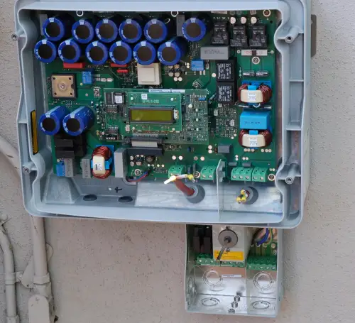
In modern transformerless string inverters and advanced off-grid hybrid inverter-chargers, the DC photovoltaic circuit is completely isolated from earth ground during normal power conversion—a topology classified under NEC 690.41 as a functionally ungrounded system. Both the positive (PV+) and negative (PV−) conductors float symmetrically with respect to ground potential. The inverter’s microprocessor continuously monitors insulation integrity by measuring differential leakage current or injecting a calibrated low-frequency AC test signal across an internal sensing network before initiating DC-to-AC conversion.
| System Topology | Ground Reference Architecture | Fault Detection Mechanism | Primary Safety Hazard |
|---|---|---|---|
| Solidly Grounded (Legacy NEC 690.5) | Negative DC conductor bonded to EGC via 0.5A–1A fuse. | Overcurrent melt of GFDI fuse in ground bond path. | Sandia Blind Spot: Faults near negative pole do not blow fuse; secondary fault causes catastrophic 1,200°C fire. |
| Functionally Ungrounded (Modern NEC 690.41) | Both PV+ and PV− float isolated from earth ground. | Active insulation resistance (Riso) sensing & residual current monitoring (RCMU). | Capacitive morning leakage trips; simultaneous dual faults bypass inverter disconnect contactors. |
| Center-Tapped Bipolar Array | Center conductor neutral grounded; ±300V or ±600V poles. | Differential current balance relays monitoring neutral return. | High voltage-to-ground shock potential (> 600V) on outer string poles. |
Understanding this operational distinction is paramount when diagnosing field errors. In a healthy functionally ungrounded array, testing with a standard 10 MΩ digital multimeter from PV(+) to ground or PV(−) to ground will yield floating, unstable, or roughly equal voltage potentials (typically 40% to 60% of total string open-circuit voltage) that gradually bleed down toward zero as the meter’s internal resistance discharges the natural parasitic capacitance of the module glass and wiring. If a solid, low-impedance copper-to-metal fault exists on either leg, the voltage reading locks into a steady, rigid value that does not decay.
2. Inverter Error Codes & Ground Fault Interlock Behavior
When an insulation failure or conductive moisture bridge develops across a solar array, the inverter acts as the primary diagnostic sensor. Different manufacturers utilize distinct diagnostic nomenclature, but all modern UL 1741-certified units perform an identical physical test sequence upon sunrise startup and during continuous grid-tied or off-grid operation:
- Pre-Startup Insulation Resistance Test (Riso Check): Prior to closing internal DC contactors or starting the high-frequency boost converter, the inverter applies a sensing potential between the combined PV conductors and ground. It calculates total isolation resistance (Riso = V / Ileakage). If Riso is less than the code-mandated 1.0 MΩ (or the manufacturer threshold, typically 100 kΩ to 1,000 kΩ), the inverter locks out with error messages such as
ISO Fault,Isolation Error, orRiso Low. - Continuous Residual Current Monitoring (RCMU): During active operation, a high-frequency current transformer (CT) encircles both the positive and negative PV conductors. By Kirchhoff’s Current Law, the instantaneous sum of incoming and outgoing DC current must equal zero (IPV+ + IPV− = 0). If current leaks from a nicked cable into the grounded roof racking, a residual differential current appears (ΔI > 30 mA to 300 mA). The inverter immediately trips within milliseconds under UL 1741B / IEC 62109-2 disconnect curves to extinguish potential arcs.
- GFDI Fuse Interruption (Grounded Inverters): On older systems, a physical blown indicator flag or error code (
Ground Fault,Error 08,GFDI Open) indicates that the 600V/1000V rated KLKD fuse between the grounded terminal block and equipment grounding conductor has vaporized.
| Inverter Brand | Common Ground Fault Display Code | Root Physical Trigger | Recommended First Field Action |
|---|---|---|---|
| SMA Sunny Boy / Tripower | Fault 3501 / Isolation Fault |
Riso < 1.0 MΩ during pre-grid connection check. | Disconnect all DC inputs; measure string Voc to PE racking. |
| SolarEdge | Error 18x8B / Isolation Error |
Optimized string impedance to ground below threshold. | Use SetApp or multimeter to read individual optimizer voltages (1V per unit). |
| Fronius Primo / Symo | State 447 / Insulation Resistance Low |
DC insulation resistance below permissible operating limit. | Verify weather conditions; check for water inside DC disconnect switch. |
| Growatt / Solis / GoodWe | PV ISO Fault / Error 08 |
Residual current spike or low insulation resistance. | Isolate paralleled MPPT channels at combiner terminal block. |
| Victron SmartSolar MPPT | Error 38 / Error 39 (PV Over-Current / Input Shutdown) |
Ground fault on solar array leading to reverse current loops. | Check battery negative to PV negative isolation; verify shunt grounding. |
When an inverter displays these warnings, amateur operators often assume the inverter’s internal electronics have failed. In more than 94% of field troubleshooting cases documented in NREL operations and maintenance databases, the inverter is functioning flawlessly as a safety monitor; the failure resides entirely out on the roof within damaged wire jackets, submerged connectors, or compromised module backsheets.

3. The Voltage-Ratio Pinpoint Method: Locating the Ruptured Module Mathematically
The most demanding physical challenge in solar field troubleshooting is identifying exactly where along a series string of 8, 12, 16, or 24 panels the cable jacket has rubbed through to bare copper against an aluminum rail. In a residential rooftop array containing three strings of 10 panels each, pulling up every module or unzipping dozens of wire ties across steep 30-degree rafters is hazardous, time-consuming, and expensive.
Fortunately, photovoltaic direct-current circuits obey fundamental Ohm’s and Kirchhoff’s circuit laws. When an ungrounded string develops a conductive ground fault, the fault location divides the total open-circuit voltage of the string into two distinct series voltage segments with respect to the equipment grounding conductor (EGC). By measuring the open-circuit voltage from the positive lead to ground, and from the negative lead to ground, a technician can mathematically calculate the exact physical panel where the insulation breach exists.
Step-by-Step Electrical Mathematical Walkthrough:
Consider an off-grid cabin installation featuring a single string of 10 monocrystalline panels connected in series. Each module possesses a nameplate open-circuit voltage (Voc) of 40.0V at current irradiance and temperature, producing an expected total array open-circuit voltage of 400.0V DC.
- Isolate the String: Switch off the inverter, open the DC disconnect, and isolate the string conductors completely from the inverter input terminals.
- Measure Overall Voc: Place the red multimeter probe on the string positive terminal and the black probe on the string negative terminal. Verify the actual total open-circuit potential:
Vstring_oc = 400.0 V DC
- Measure Positive-to-Ground: Place the black meter probe firmly on the bare copper equipment grounding conductor (or grounded aluminum rail) and touch the red probe to the String Positive (+) lead:
V(+)-to-GND = +120.0 V DC
- Measure Negative-to-Ground: Keep the black meter probe on the equipment grounding conductor and touch the red probe to the String Negative (−) lead:
V(−)-to-GND = −280.0 V DC (Magnitude = 280.0 V)
- Verify Voltage Summation: Verify that the sum of the absolute values equals total measured string open-circuit voltage:
|V(+)-to-GND| + |V(−)-to-GND| = 120.0V + 280.0V = 400.0V = Vstring_oc
- Apply the Pinpoint Location Ratio: Calculate the module index (Nfault) counting sequentially from the Negative string home-run terminal:
Nfault = Ntotal × [ V(−)-to-GND / Vstring_oc ]
Nfault = 10 × ( 280.0V / 400.0V ) = 10 × 0.70 = Module #7
The mathematical result demonstrates that the fault is located exactly 7 modules away from the negative home-run lead (which is equivalent to 3 modules away from the positive lead). Instead of dismantling all 10 panels, the technician immediately walks directly to Module #7, unbolts the mid-clamps, lifts the frame, and inspects the cable run. In real-world applications, this mathematical pinpointing saves hours of labor and eliminates unnecessary roof traffic that can crack fragile solar wafers.
⚠ High-Voltage DC Shock & In-Line Arc Flash Warning
Solar photovoltaic strings cannot be switched off by turning off an inverter—modules remain live and generate lethal DC voltages (up to 600V in residential and 1,000V in commercial arrays) whenever exposed to sunlight. When troubleshooting a ground fault, always use a CAT III/IV 1,000V-rated digital multimeter with insulated test probes. Never disconnect MC4 connectors under load or while a ground fault is active; breaking live DC circuits creates a sustained plasma arc that will not extinguish naturally at atmospheric pressure, vaporizing contact pins and causing severe flash burns.
⚡ Solar String Ground Fault Pinpoint & Isolation Resistance (Riso) Calculator
Enter your series string configuration and multimeter voltage-to-ground measurements to mathematically pinpoint the faulted panel and determine insulation resistance compliance.
Series panels in the faulted circuit
STC open-circuit voltage from datasheet
Positive terminal to racking earth
Negative terminal to racking earth
Module #7
400.0 V
< 50 kΩ (Critical)
NON-COMPLIANT (Trip)
Direct Amazon Link
Precision electrical troubleshooting of solar arrays requires true-RMS CAT III/IV 600V–1,000V rated meters capable of detecting millivolt ground differentials and non-contact DC leakage currents without arcing hazards:
CAT III 600V rated auto-ranging digital multimeter engineered for high-precision DC voltage-to-ground ratio testing and open-circuit Voc verification across residential strings.
Non-contact 600A AC/DC clamp meter for measuring continuous leakage current over equipment grounding conductors (EGC) and verifying string operating amperage under load.
5. Insulation Resistance (Riso) Testing with a Megohmmeter (Megger Protocol)
While a digital multimeter is exceptional for calculating voltage ratios on energized strings under daylight, it cannot accurately test the dielectric integrity of non-energized conductors. Standard multimeters utilize a low-voltage internal battery (typically 9V or two 1.5V AA cells) that is incapable of stressing cable insulation or overcoming high micro-gap contact resistances. A wire that reads open-circuit (> 20 MΩ) on a handheld multimeter can experience catastrophic dielectric breakdown when subjected to 400V or 800V DC operational voltages.
To definitively prove conductor health per international standard IEC 62446-1 Section 6.2, commissioning technicians and forensic investigators use an insulation resistance tester (commonly referred to in the electrical trades as a Megger). An insulation tester generates a regulated high-voltage DC test signal (250V, 500V, or 1,000V) and measures micro-amperes of leakage current to calculate true mega-ohm dielectric resistance (Riso).

The Two Standardized Test Methods:
- Method 1: Test Between Short-Circuited Array Terminals and Earth (Standard Commissioning): Both the Positive and Negative string home-run cables are connected together via a temporary jumper switch. The positive megohmmeter lead is connected to this jumper, and the negative meter lead is bonded to the equipment grounding conductor (EGC) or grounding electrode system. The test voltage is applied for 60 seconds until capacitive charging current stabilizes. Under IEC 62446, minimum acceptable resistance for arrays operating above 120V is 1.0 MΩ.
- Method 2: Test Individual Isolated Conductors (Array Disconnected): In this method, individual string home-run conductors running through underground conduit or metallic EMT are disconnected at both ends (combiner box and inverter). The test voltage is applied between each isolated conductor core and the metallic conduit wall to identify insulation chafing caused by wire pulls or sharp conduit burrs.
| System Maximum Voltage (Vdc) | Mandatory Test Voltage (Vdc) | Minimum Acceptable Riso (IEC 62446) | Real-World Healthy Benchmark |
|---|---|---|---|
| < 120 V DC (12V/24V/48V Battery Arrays) | 250 V DC or 500 V DC | ≥ 0.5 MΩ (500 kΩ) | > 20 MΩ to 100 MΩ |
| 120 V DC to 500 V DC (Residential String MPPTs) | 500 V DC | ≥ 1.0 MΩ (1,000 kΩ) | > 50 MΩ to 200 MΩ |
| > 500 V DC to 1,000 V DC (Commercial Off-Grid / High-Voltage Strings) | 1,000 V DC | ≥ 1.0 MΩ (1,000 kΩ) | > 100 MΩ to > 1 GΩ |
💡 Engineering Pro-Tip: Diagnosing Morning “Ghost” Isolation Trips
If your inverter trips with an “ISO Fault” or “Riso Low” only during early morning hours and then magically clears by 10:00 AM once the sun is high, you are facing a moisture-induced capacitive leakage fault rather than a dead metal short. Morning dew, frost, and high humidity create a conductive water film across dusty panel glass and micro-cracked MC4 rubber seals. Check for connectors lying flat on the roof surface without proper drip loops; elevating all wire runs off the roof deck using stainless steel PV cable clips immediately restores insulation resistance above the mandatory 1.0 MΩ threshold.
6. Common Root Causes: Moisture Ingress, Cable Pinching & Mechanical Abrasion
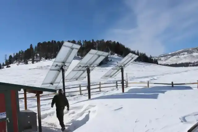
Photovoltaic modules operate in harsh environmental conditions characterized by extreme thermal cycling (−30°C in winter to +70°C module operating temperatures in summer), high UV irradiance, wind-induced mechanical vibration, and heavy snow loading. Decades of PV reliability analyses conducted by Sandia National Laboratories and the National Renewable Energy Laboratory (NREL) classify ground fault causes into four primary categories:

1. Cable Chafing Against Sharp Aluminum Mounting Rails:
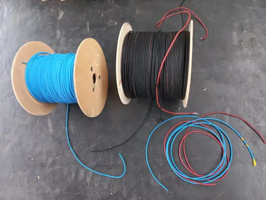
When installers pull sunlight-resistant PV wire (such as 10 AWG or 12 AWG USE-2 / PV Wire) across extruded aluminum racking channels without securing conductors every 4 to 6 feet, wind vibration creates persistent micro-motion. Over 3 to 7 years, sharp mill-finished aluminum extrusion burrs saw cleanly through the outer cross-linked polyethylene (XLPO) insulation jacket. The moment bare stranded copper contacts the grounded rail, a solid, permanent ground fault is established.
2. MC4 Connector Submersion & Seal Degradation:
Standard Multi-Contact MC4 plugs carry an IP67 or IP68 water ingress rating when properly assembled and clicked together with genuine matching manufacturer pins. However, when installers mix mismatched brand connectors (e.g., plugging an Amphenol H4 plug into a Staubli MC4 socket) or allow connectors to lie horizontally inside roof tile valleys where standing water pools during rainstorms, capillary action draws moisture past rubber O-rings. The wet internal air gap becomes conductive, leaking current to the grounded roof deck.
3. Rodent & Wildlife Damage (Squirrels & Birds):
In residential rooftop solar arrays, the protected, warm cavity beneath solar panels offers ideal nesting habitat for squirrels, roof rats, and pigeons. Rodents possess continuously growing incisors and gnaw aggressively on plastic conduit fittings and double-insulated PV wire jackets. Chewed insulation exposes live copper directly to the underside of grounded anodized aluminum module frames.
4. Internal Module Backsheet Delamination & Cracked Glass:
Hail impacts, heavy wet snow accumulations, or thermal stress micro-cracks can rupture the tempered solar front glass or degrade the rear polymer backsheet (Tedlar/PET). When moisture penetrates the EVA encapsulant, leakage current flows from internal solar cell interconnect ribbons directly to the grounded perimeter aluminum frame, triggering low-insulation resistance interlocks even though external wiring appears pristine.
Switch off the inverter AC output breaker and open the main DC disconnect switch. Do not disconnect series MC4 connectors while under load. Verify with a calibrated clamp meter that current through the equipment grounding conductor (EGC) has dropped to 0.0A before opening combiner boxes.
In multi-string systems, open all DC string fuses or circuit breakers in the combiner enclosure. When multiple strings share a common DC busbar, a single ground fault skews the ground reference across all paralleled strings. Isolating each string independently eliminates phantom fault crosstalk.
Using a CAT III/IV digital multimeter set to DC Volts, connect the black probe securely to the bare copper equipment grounding conductor (EGC) or aluminum racking frame. Probe the Positive (+) terminal, then probe the Negative (−) terminal. A healthy string shows floating symmetrical voltages. The string displaying full Voc on one pole and near 0V on the opposite pole is your faulted string.
Apply the voltage-divider formula: Nfault = Ntotal × [ V(−)-to-GND / ( V(+)-to-GND + V(−)-to-GND ) ]. If testing a 10-panel string with 120V on (+) and 280V on (−), the fault is mathematically localized to Module #7. Target your physical roof ladder climb directly to Module #7.
At the localized module, inspect wire clips, conduit entry points, and junction box seals. Look for conductors pinched beneath module frames, sharp burrs on aluminum mounting rails rubbing through double-insulated XLPO cable jackets, and moisture ingress in MC4 plugs. Replace compromised cables or install listed UV-resistant heat-shrink tubing and secure wires with stainless steel PV wire clips.
Before reconnecting the string to the inverter, perform an insulation resistance test with a digital megohmmeter set to 1,000V DC per IEC 62446-1. Connect active conductors together and test against earth ground. Verify that insulation resistance exceeds 1.0 MΩ (healthy strings routinely read > 50 MΩ). Reclose combiner fuses, close the DC disconnect, and clear the inverter error log.