Yes, you can mix different wattage solar panels, but you cannot simply add their rated wattages together on a single charge controller. In a series string, the entire array is bottlenecked to the lowest panel’s operating current (Imp), causing massive power waste. In a parallel array, voltages must match within 5% to prevent heavy clipping losses.
Connecting an older 100W solar panel (18V, 5.5A) in series with a new 300W solar panel (32V, 9.4A) gives you a combined 400-Watt solar array (100W + 300W = 400W).
In a series circuit, current is identical through every conductor. The 100W module forces the entire string down to 5.5 Amps. The 300W module can only produce 32V × 5.5A = 176W. Your total array output drops to 275W, throwing away over 125W (31% system loss) as unharvested energy and heat.
1. The Physics of Solar Module Mismatch: Current Bottlenecks vs. Voltage Clamping
When designing or expanding an off-grid solar power system, adding newer, higher-wattage panels to an existing array is one of the most common DIY dilemmas. Homeowners, cabin builders, and RV owners frequently acquire newer 200W, 300W, or 400W panels while still possessing perfectly functional 100W panels. To understand whether these panels can be combined safely and effectively, we must examine the governing physics of photovoltaic current-voltage (I–V) curves.
A solar panel is not a fixed-voltage battery or an infinite AC generator; it is a semi-conductor current source controlled by solar irradiance, silicon junction temperature, and internal series resistance (Rs). Two critical specifications define every solar module’s maximum power point (MPP) under Standard Test Conditions (STC: 1,000 W/m² irradiance, 25°C cell temperature, AM 1.5 spectrum):
- Maximum Power Voltage (Vmp): The operating voltage at which the module delivers its peak electrical wattage. Typically ~18V to 20V for nominal 12V modules (36 cells), ~30V to 36V for 60-cell modules, and ~40V to 44V for 72-cell / 144-half-cut commercial modules.
- Maximum Power Current (Imp): The operating amperage at which the module delivers peak electrical power. Typically ~5.5A for 100W panels, ~9.5A for 300W panels, and ~13A to 14A for modern 450W+ residential panels.
When you combine solar panels of differing wattages onto a single Maximum Power Point Tracking (MPPT charge controller), Kirchhoff’s Laws strictly dictate the electrical consequences depending on whether you choose series or parallel wiring.
Empirical photovoltaic research from the National Renewable Energy Laboratory (NREL) demonstrates that if two parallel solar strings possess Maximum Power Voltages (Vmp) within 5% of each other, the net array power loss remains under 1.8%. When mixing mismatched wattages, parallel wiring is mathematically and physically superior to series wiring in over 90% of field installations.
2. Mixing Mismatched Solar Panels in Series: The Current Bottleneck Disaster
In a series electrical circuit (daisy-chaining the positive lead of Panel 1 into the negative lead of Panel 2), voltages add arithmetically, while amperage must remain uniform across the entire conductor loop:
According to research by Sandia National Laboratories on module mismatch inefficiencies (SAND2012-10444C / OSTI ID: 1073574), connecting panels with differing current ratings forces the string current to collapse to the capability of the lowest-amperage module in the loop. The higher-rated module cannot push its full current through the smaller p-n junctions of the smaller module without forcing those cells into reverse bias.
Mathematical Demonstration: 100W Panel + 300W Panel in Series
Consider a practical scenario where a system owner connects an existing 100-Watt panel in series with a newly acquired 300-Watt panel:
| Specification | Module A (100W Legacy) | Module B (300W New) | Theoretical Sum | Actual Series Output |
|---|---|---|---|---|
| Rated Power (Pmax) | 100 W | 300 W | 400 W | 275 W |
| Voltage at MPP (Vmp) | 18.0 V | 32.0 V | 50.0 V (18V + 32V) | 50.0 V |
| Current at MPP (Imp) | 5.55 A | 9.38 A | — | 5.55 A (Choked!) |
| Harvest Efficiency | 100% (100W output) | 58.7% (176W output) | 100% | 68.75% (-125W Lost!) |
As demonstrated in the table above, the 300-Watt panel is artificially choked from its design current of 9.38 Amps down to 5.55 Amps. It produces only 32V × 5.55A = 177.6W. You have purchased a 300-Watt panel but are utilizing it as if it were a 175-Watt module, permanently wasting 122.4 Watts of expensive solar capacity whenever the sun shines.
When high-current mismatch occurs in a series string, the MPPT charge controller attempts to sweep the I-V curve to maximize total wattage. If the controller draws current exceeding the 100W panel’s photocurrent generation (I > 5.55A), the smaller panel’s cells are driven into negative reverse-bias voltage. This forces the panel’s internal bypass diodes into continuous heavy conduction, causing extreme diode junction temperatures exceeding 125°C (257°F), accelerating junction box melting, EVA delamination, and permanent cell micro-cracking.
3. Mixing Mismatched Solar Panels in Parallel: The Preferred Mathematical Route
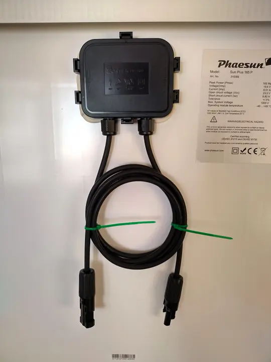
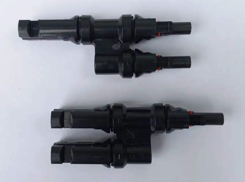
In a parallel electrical circuit (combining positive terminals together and negative terminals together using multi-branch MC4 combiners or a solar combiner box), amperages add arithmetically, while the operating voltage is constrained across the common bus:
When two parallel strings share a single MPPT charge controller input, the MPPT controller can only select a single operating voltage for the entire array. It will search for the combined Global Maximum Power Point (GMPP), which settles at a weighted compromise between the Vmp of the two panels.
Parallel Scenario 1: Same Voltage, Different Wattage (The Ideal Match)
Consider mixing a 100-Watt panel (18.0V Vmp, 5.55A Imp) with a 200-Watt panel (18.2V Vmp, 11.0A Imp). Both modules are engineered as nominal 12V panels with 36 monocrystalline cells:
- Operating Voltage Delta: ΔV = |18.2V – 18.0V| = 0.2V (a negligible 1.1% divergence).
- Combined Current: I_{total} = 5.55A + 11.0A = 16.55A.
- Total Power Output: Operating at ~18.1V, the array delivers 18.1V × 16.55A = 299.5W out of an absolute theoretical 300.0 Watts.
- Net Mismatch Loss: Less than 0.2%. The panels work in near-flawless harmony!
Parallel Scenario 2: Different Voltage and Different Wattage (Severe Loss)
Now consider mixing that same 100-Watt panel (18.0V Vmp, 5.55A Imp) in parallel with a 300-Watt residential panel (32.0V Vmp, 9.38A Imp):
- Operating Voltage Delta: ΔV = |32.0V – 18.0V| = 14.0V (a massive 43.7% divergence).
- The MPPT Dilemma: If the MPPT operates at 18V to harvest the 100W panel, the 300W panel is forced far to the left of its knee curve, dropping from 300W down to ~168W. If the MPPT operates at 32V, the 100W panel produces zero current because 32V exceeds its open-circuit voltage (V_{oc} ≈ 22V).
- Net Array Output: ~220W to 240W total (out of 400W theoretical). You lose roughly 40% of your total solar harvest.
4. Technical Comparison Matrix: Series vs. Parallel Mismatch Outcomes
The following engineering matrix outlines the four primary mismatch scenarios encountered in field installations, detailing current flow, voltage behavior, and recommended system architecture:
| Wiring Topology | Electrical Condition | Primary Bottleneck | Estimated Loss (%) | Field Recommendation |
|---|---|---|---|---|
| Series | Same Wattage, Different Brand | Minor Imp deviation (<0.5A) | 1% – 4% | Permissible: Safe for field operation. |
| Series | Different Wattage (e.g. 100W + 300W) | Severe Imp bottleneck (Imin) | 25% – 50% | Prohibited: Massive waste & diode heat. |
| Parallel | Different Wattage, Same Vmp (±5%) | None; Amperages add linearly | < 2% | Highly Recommended: Optimal configuration. |
| Parallel | Different Wattage, Different Vmp (>10%) | Voltage clamping / curve distortion | 20% – 45% | Avoid: Requires dual charge controllers. |
5. The Three Approved Engineering Solutions for Mixing Mismatched Panels
If you already own solar modules of varying sizes, brands, or wattages and refuse to accept catastrophic power losses, three standard electrical engineering architectures solve the mismatch problem completely:
Solution 1: Deploy Dual Charge Controllers on One Battery Bank (The Gold Standard)
As documented in our comprehensive engineering guide to multiple charge controllers on one battery bank, the cleanest and most efficient method to mix mismatched panels is to separate them into dedicated arrays, each managed by its own independent MPPT controller:
- Array 1: Your legacy 100W modules wired in series-parallel, connected to MPPT Controller 1.
- Array 2: Your new 350W modules wired in a high-voltage series string, connected to MPPT Controller 2.
- Common Busbar: Both controllers output DC current to a centralized battery busbar, charging the battery bank simultaneously with zero cross-interference and 100% harvest efficiency.
Solution 2: DC Power Optimizers or Microinverters
In grid-tied or modern hybrid systems, installing module-level power electronics (MLPE) such as SolarEdge DC power optimizers or Enphase microinverters isolates each module electrically. Each optimizer performs MPPT tracking on its specific panel before outputting constant current or AC power, completely eliminating string mismatch penalties.
Solution 3: Matched Sub-Arrays in Parallel
If purchasing a second controller is not feasible, you can build identical series strings out of different panels. For example, two 100W panels wired in series (18V + 18V = 36V) can be wired in parallel with a single 300W panel (V_{mp} = 36V). Because both parallel branches share an identical 36V operating point, the array operates at over 98% efficiency!
6. Bypass Diode Thermal Dissipation & Junction Box Failure Physics
To fully grasp why severe current mismatch in series strings poses a catastrophic fire and reliability hazard, we must examine the internal semiconductor mechanics of photovoltaic junction boxes. Commercial solar panels are divided into three or four series cell groups, each protected by an antiparallel bypass diode (typically a Schottky barrier diode, such as a 15SQ045 or 20SQ045 rated for 15A–20A and 45V reverse breakdown).
Under uniform solar irradiance with matched modules, every solar cell is forward-biased, generating positive photocurrent (Iph). In this normal state, the bypass diodes experience reverse bias from the cell string voltage and remain completely non-conductive, drawing only negligible nanoampere leakage current (I_{leak} < 50,µA).
However, when a 100W panel (I_{mp} = 5.55A) is placed in series with a 350W panel (I_{mp} = 10.5A), a severe operating conflict emerges whenever an MPPT charge controller attempts to extract peak string power:
- Forced Reverse Bias: The 350W module attempts to drive 10.5 Amps through the circuit. Because the 100W module’s silicon cells physically cannot generate more than 5.55A of photocurrent under 1,000 W/m² irradiance, the surplus 4.95 Amps forces the smaller cells into reverse-bias breakdown (V_{cell} < 0).
- Continuous Diode Conduction: Once reverse bias reaches approximately -0.5V to -0.7V per cell group, the internal Schottky bypass diodes are forced into continuous forward conduction to divert the excess current around the bottlenecked cells.
- Thermal Calculation (P = I × Vf): Standard Schottky bypass diodes feature a forward voltage drop (Vf) between 0.45V and 0.60V under heavy current. With 10.5 Amps flowing through the diode:
Pthermal = Iforward × Vf = 10.5A × 0.55V = 5.78 Watts
If all three bypass diodes in the junction box are conducting, the sealed plastic enclosure must dissipate over 17.3 Watts of continuous pure heat.
- Junction Breakdown Temperature: Most PV junction boxes are small, non-ventilated polycarbonate enclosures mounted directly to the thermal backsheet. Laboratory studies published by Sandia National Laboratories indicate that sustained dissipation exceeding 10 Watts causes internal junction box temperatures to soar beyond 135°C (275°F). This thermal overload melts plastic casings, decomposes potting silicone, causes solder joint thermal fatigue, and culminates in permanent diode short-circuit failure—rendering one-third or all of the solar panel permanently dead.
7. The Multi-Knee I-V Curve: Why Standard MPPT Controllers Get Trapped
A second severe consequence of mixing mismatched solar panels on a single controller is the creation of complex, multi-peaked power-voltage (P-V) curves. When identical panels are wired together, the resulting P-V curve features a single smooth parabolic curve with exactly one global maximum power point (GMPP). The charge controller’s algorithm easily tracks this single peak using simple Perturb and Observe (P&O) tracking.
However, when panels with differing voltages and currents are combined, the composite electrical characteristic develops multiple local maxima (multiple “knees”):
- Local Peak A (Low Voltage, High Current): Occurs when the controller sweeps down to the voltage of the smaller panel, allowing all panels to conduct, but sacrificing the high voltage of the larger panel.
- Local Peak B (High Voltage, Low Current): Occurs when the controller sweeps up to the voltage of the larger panel, but forces the smaller panel into open-circuit shutdown or bypass diode conduction, cutting total current in half.
Budget MPPT charge controllers (and nearly all PWM controllers) lack advanced full-voltage sweep routines. When irradiance shifts or morning sun rises, a basic controller tracking upward from zero volts encounters Local Peak A. Because the power drops slightly if it moves either left or right of Peak A, the controller’s simple gradient logic assumes it has found the true maximum power point. It locks onto Peak A, producing perhaps 180 Watts, while completely oblivious to the fact that just 15 Volts higher sits the true Global Maximum Power Point (GMPP) capable of delivering 310 Watts!
To avoid this software trapping penalty, system owners mixing panels must utilize advanced controllers with periodic full-spectrum curve scanning capabilities, such as Victron Energy’s BatteryLife with Global Sweeping or SMA’s OptiTrac Global Peak, which periodically sweep the entire voltage window from Vbattery to Voc every 10 minutes.
8. Real-World Engineering Field Scenarios & Reconfiguration Walkthroughs
To see these mathematical principles applied to actual off-grid hardware, consider two classic field expansion dilemmas frequently encountered by off-grid builders:
Case Study 1: The Campervan Rooftop Dilemma (Two 100W Panels + One 200W Panel)
A van lifer originally installed two 100W 12V monocrystalline panels (V_{mp} = 18.2V, I_{mp} = 5.50A). Seeking more power for an induction cooktop, they add one 200W panel (V_{mp} = 20.4V, I_{mp} = 9.80A) to available roof space. How should these three modules be wired into a single Victron SmartSolar 100/30 MPPT controller?
- Wrong Series Approach: Wiring all three in series (100W + 100W + 200W) yields V_{string} = 18.2 + 18.2 + 20.4 = 56.8V. However, string current is bottlenecked to the 100W panel’s 5.50A. Total harvest: 56.8V × 5.50A = 312.4W. You lose 87.6 Watts (21.9% total system penalty)!
- Correct Hybrid Series-Parallel Approach: Wire the two 100W panels in series to create a single 200W branch (V_{branch1} = 18.2 + 18.2 = 36.4V, I_{branch1} = 5.50A). Then wire this branch in parallel with the 200W panel. But wait! The 200W panel’s Vmp is only 20.4V, creating a huge 16V delta (36.4V vs 20.4V). This would cause massive parallel clipping!
- The Winning Pure Parallel Topology: Wire the two 100W panels in parallel (V_{mp} = 18.2V, I = 11.0A). Then wire them in parallel with the 200W panel (V_{mp} = 20.4V, I = 9.80A). The voltage delta is |20.4V – 18.2V| = 2.2V (only 10.7%). The combined array settles at an intermediate ~19.3V, delivering 19.3V × (11.0A + 9.80A) × 0.96 ≈ 385W out of 400W theoretical! Net loss is under 3.7%—a massive victory compared to the series bottleneck.
Case Study 2: The Off-Grid Cabin Array (Four 250W Residential Panels + Two 400W Commercial Panels)
A cabin owner has four legacy 250W 60-cell panels (V_{mp} = 30.5V, I_{mp} = 8.20A) and acquires two new 400W 144-half-cut panels (V_{mp} = 41.2V, I_{mp} = 9.71A). Total nameplate capacity is 1,000W + 800W = 1,800W:
- Current Matching Discovery: Notice the current ratings: 8.20A vs 9.71A. The current delta is |9.71A – 8.20A| / 8.95A = 16.8%. Wiring them in series wastes 15.5% of the 400W panels’ capability.
- Voltage Matching Discovery: In parallel, 30.5V vs 41.2V creates a severe 26% voltage delta. Wiring them directly in parallel wastes over 28% of total capacity.
- The Engineering Solution: Because neither series nor parallel produces acceptable efficiency, this system strictly mandates Solution 1 (Dual MPPT Controllers). Dedicated Controller 1 manages the four 250W panels in a 2S2P configuration (61V, 16.4A), while Controller 2 manages the two 400W panels in a 2S configuration (82.4V, 9.71A). Both feed the common 48V battery bank, delivering a full 1,800 Watts with 100% harvest efficiency.
9. Interactive Calculator: Mismatched Solar Panel Series vs. Parallel Loss Simulator
Use our field-calibrated engineering calculator below to model the real-world output, power loss percentage, and optimal wiring topology when combining two different solar panel models on a single charge controller:
⚡ Mismatched Solar Panel Series vs. Parallel Loss Calculator
Panel Group 1 (e.g. Existing / Smaller Modules)
Panel Group 2 (e.g. New / Larger Modules)
Simulation Results
10. Field Commissioning SOP Checklist for Mismatched Solar Arrays
Before energizing any off-grid installation combining non-identical solar panels, follow this systematic commissioning procedure to ensure code compliance, prevent wire overheating, and protect equipment:

- Step 1: Record All Nameplate Specifications: Photograph and document the Voc, Vmp, Isc, Imp, and Maximum Series Fuse Rating from the rear sticker of every module.
- Step 2: Calculate Percentage Voltage Divergence: If wiring in parallel, compute ΔV = |V_{mp1} – V_{mp2}| / V_{mp,avg}. Confirm divergence is strictly under 5%. If divergence exceeds 10%, abort parallel wiring on a single controller.
- Step 3: Calculate Percentage Current Divergence: If wiring in series, compute ΔI = |I_{mp1} – I_{mp2}| / I_{mp,avg}. Confirm divergence is under 3%. If divergence exceeds 5%, abort series wiring.
- Step 4: Install Branch Overcurrent Protection (NEC 690.9): When paralleling three or more strings, install an inline fuse sized at 1.56 × I_{sc} on each string to prevent backfeed fault currents from incinerating lower-amperage conductors.
- Step 5: Verify Conductor Ampacity (NEC 690.8): Ensure your combined parallel trunk cable (typically 10 AWG or 8 AWG) is rated for 1.25 × 1.25 × sum I_{sc} continuous current. Refer to our solar wire size calculator for exact gauge sizing.
- Step 6: Perform Open-Circuit Polarity & Voltage Sweep: Using a calibrated digital multimeter (DMM), measure string open-circuit voltage (Voc) under unshaded noon sun. Confirm voltage matches predicted mathematical models.
- Step 7: Conduct Thermal Clamp-Meter & Infrared Inspection: Energize the system and apply full load. Use a DC clamp meter to measure individual string currents, and use an infrared thermal camera to verify that no panel junction box or bypass diode exceeds 80°C (176°F).
11. Frequently Asked Questions (PAA Search Schema)
Can I mix a 100W and a 200W solar panel?
Yes, provided you wire them in parallel and their Maximum Power Voltages (Vmp) match closely (both typically ~18V). In parallel, their currents will add safely (5.5A + 11.0A = 16.5A), delivering ~295W to 300W total with less than 2% loss. Do NOT wire them in series, as the 100W panel will choke the 200W panel to half power.
Can I mix different brands of solar panels of the same wattage?
Yes. Mixing two 200W panels from different brands (e.g., Renogy and Rich Solar) is completely safe in either series or parallel, provided their Vmp and Imp ratings are within 3% of each other. Minor variances will result in less than 1% harvest loss.
Can I mix monocrystalline and polycrystalline solar panels?
Yes. Monocrystalline and polycrystalline cells generate DC electricity using identical photovoltaic principles. However, monocrystalline panels generally feature slightly higher Vmp and lower temperature coefficients than older poly panels. Compare their actual nameplate Vmp and Imp ratings rather than their silicon crystal structure.
Will mixing different wattage panels damage my solar charge controller?
No. An MPPT charge controller only senses the total incoming array voltage (Vin) and limits incoming current (Iin). It does not know or care if current arrives from one panel or ten mismatched panels. However, you must obey the controller’s Maximum Input Voltage (Vocmax) to prevent electrical hardware damage.
Do I need blocking diodes when mixing mismatched solar panels?
In modern photovoltaic systems, blocking diodes are generally unnecessary because silicon solar cells only backfeed significant current if string voltage differences exceed the open-circuit voltage (Voc), or during ground faults. Instead, the National Electrical Code (NEC Article 690.9) mandates appropriately sized branch circuit fuses (1.56 × I_{sc}) when three or more parallel strings are combined.