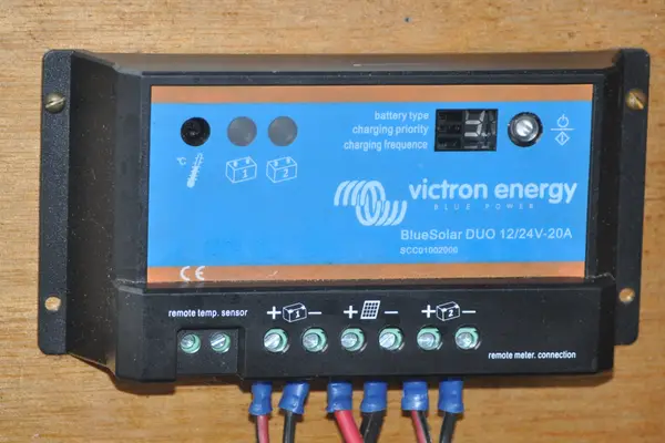
Yes, you can safely connect multiple solar charge controllers—including two or more Maximum Power Point Tracking (MPPT) units—to a single battery bank. In off-grid electrical engineering, this configuration is known as a multi-controller parallel charging topology. Each charge controller operates as an independent, unidirectional DC-to-DC step-down buck converter. Rather than interfering with or backfeeding one another, each controller monitors the common terminal voltage of the battery bank and adjusts its pulse-width modulation (PWM) switching duty cycle accordingly to supply available solar harvest.
However, running multiple charge controllers without proper circuit architecture introduces real electrical hazards: unequal conductor resistance causing premature absorption transitions, catastrophic overcurrent violations that exceed lithium battery management system (BMS) charge ratings, and dangerous ground-fault circulating currents. Executing a safe dual or triple MPPT installation requires strict adherence to four foundational engineering mandates:
- Completely Isolated PV String Inputs: Solar panel strings must never be cross-connected between different controllers. Each MPPT must have its own dedicated, galvanically isolated photovoltaic array.
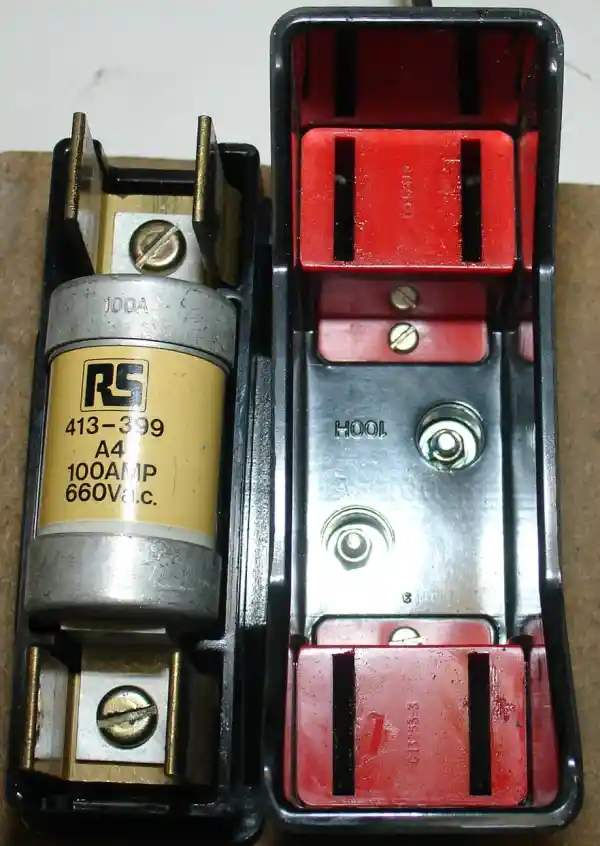
- Common Low-Resistance DC Busbars: Output cables from each charge controller must land on a central, heavy-duty busbar rather than stacking multiple lugs onto the physical battery posts.
- Identical Multi-Stage Voltage Calibration: Bulk, Absorption, and Float voltage thresholds must be programmed within ±0.05V across all units to prevent “premature float lockout.”
- Total Combined Current Verification: The sum of all controller maximum output currents must never exceed the continuous charge acceptance limit of the battery bank (Icombined ≤ Crate × Capacity).
“If you connect two charge controllers to the same battery without a communication cable, they will fight each other, backfeed current into the lower-output unit, and burn out the internal MOSFET power transistors.”
Charge controllers feature internal unidirectional synchronous FETs or reverse-blocking Schottky diodes that physically prevent current from flowing backward into the output terminals. Each controller simply reads the shared battery terminal voltage; current naturally flows from the higher potential of the controllers into the lower chemical potential of the battery bank.
1. Operating Physics: How Multiple Charge Controllers Interact
To understand why multiple charge controllers do not “fight” or destroy each other, we must examine the internal semiconductor topology of modern MPPT hardware. An MPPT charge controller is fundamentally a high-frequency switch-mode DC-DC buck converter. It takes a higher input DC voltage from the photovoltaic string (typically 40V to 150V+ DC) and steps it down to the lower DC voltage required by the battery bank (12V, 24V, or 48V nominal), while boosting the charging current proportionally according to the law of conservation of power (P = V × I).
The output stage of every quality charge controller utilizes an array of high-current N-channel MOSFETs configured for synchronous rectification. Crucially, these output stages operate in quadrant I of the IV electrical plane—meaning they can only source current, never sink it. When Controller A outputs 40 Amps at 14.2V and Controller B outputs 25 Amps at 14.2V, the battery bank simply acts as a common electrical sump. According to Kirchhoff’s Current Law (KCL), the algebraic sum of currents entering a common node equals the sum of currents entering the battery:
Because the internal resistance (Rint) of a deep-cycle lithium (LiFePO4) or lead-acid battery is exceptionally low (typically between 1 to 15 milliohms), both controllers can pump maximum current simultaneously into the battery without significant voltage rise during the Bulk (constant current) charging phase.
2. Why Off-Grid Systems Require Multiple Charge Controllers
Why not simply install a single, gigantic 100A or 150A charge controller? In real-world off-grid engineering, splitting your solar array across multiple independent charge controllers is often mathematically and practically superior:
| Engineering Scenario | Single Large MPPT Controller | Dual / Multi-MPPT Architecture |
|---|---|---|
| Different Roof Pitches & Orientations | Severe string mismatch losses; array output pulled down to worst-performing string. | Full Peak Harvest: East-facing panels on Controller 1; West-facing panels on Controller 2. |
| Partial Shading (Trees, Chimneys) | Shade on one panel triggers bypass diodes across entire series string; drops MPPT tracking efficiency. | Localized Isolation: Shaded array on MPPT 1 does not drag down full harvest on unshaded MPPT 2. |
| Mixed Solar Panel Models | Violates string voltage/current matching rules; leads to severe thermal hot-spotting. | Complete Compatibility: Old 250W panels on Controller 1; new 450W bifacial panels on Controller 2. |
| System Redundancy (Critical Loads) | Single point of catastrophic failure; controller shutdown drops 100% of solar generation. | Fault Tolerance: If Controller 1 fails, Controller 2 continues generating power to preserve battery state-of-charge. |
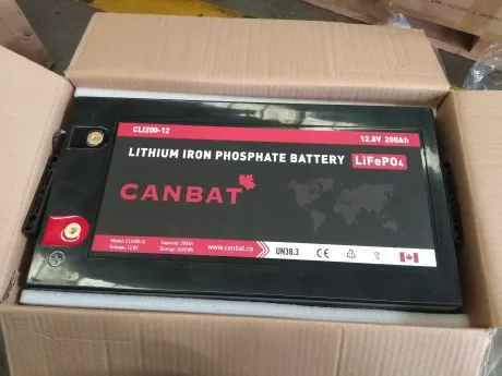
Never assume a battery bank can accept unlimited current simply because you add more charge controllers. Most 12V 100Ah drop-in LiFePO4 batteries carry a continuous charge current rating of 50A (0.5C), with a hard BMS overcurrent cutoff threshold at 100A. If you wire two 40A MPPT controllers together, their combined 80A peak output will exceed the 50A recommended limit on a single 100Ah battery, triggering accelerated cell degradation or sudden BMS emergency cutoff! Always ensure your total battery Ah capacity satisfies:
Total Ah ≥ Combined Amps ÷ Maximum C-Rate.
Enter your charge controller ratings and battery bank specifications below to verify combined charging current, C-rate safety margins, and minimum busbar ratings.
70.0 Amps
2,016 Watts
0.35 C
87.5 Amps (Use 150A+ Bar)
✅ SAFE: Well within 0.5C LiFePO4 limits
3. The 4 Non-Negotiable Wiring Mandates for Multiple Controllers
Wiring two charge controllers requires a strict systematic approach. Grounding errors, unequal wire lengths, or common-PV mistakes will permanently damage components. Review and enforce these four foundational rules:
Rule 1: Galvanic Isolation of Photovoltaic (PV) Inputs
Never parallel the solar panel inputs between two controllers. Each MPPT algorithm searches for the peak power point by varying its internal impedance and observing the corresponding change in array voltage and current (dP/dV = 0). If you parallel the solar inputs of Controller 1 and Controller 2 to the same string of panels, their high-frequency tracking sweeps will oscillate against one another, causing severe harmonic instability, hunting errors, and a 30% to 50% loss in power extraction. Array 1 goes exclusively to Controller 1; Array 2 goes exclusively to Controller 2.
Multi-controller setups allow you to bypass manufacturer string matching constraints. For example, if you have four 100W flexible panels mounted on an RV roof (Vmp 18V) and four 350W rigid residential panels mounted on ground deployment brackets (Vmp 38V), wiring them to a single controller would choke the system. By routing the roof panels to a 30A MPPT and the ground panels to a separate 60A MPPT, both systems operate at their independent, 100% peak theoretical efficiency!
Rule 2: Dedicated Busbars Over Battery Post Stacking
In novice DIY systems, installers often attempt to land the output cables from Controller 1, Controller 2, the inverter, and DC fuse blocks all onto the physical lead or brass studs of the battery bank. Never stack multiple high-current ring terminals on battery posts.
Terminal stacking creates elevated electrical resistance across the metal interfaces (Rcontact = ρ / A). Under high charging current, this contact resistance causes localized resistive heating (P = I2R), creating a fire hazard and throwing off the controller’s voltage-sensing accuracy. National Electrical Code (NEC 690.9 and NEC 705) mandates landing all charging sources onto dedicated, positive and negative heavy-duty copper busbars sized for the total continuous ampacity of all connected circuits.
Rule 3: Symmetrical Wire Sizing and Voltage Drop Minimization
Both charge controllers must reach the central DC busbar with minimal conductor resistance. If Controller A is wired with 10 feet of 10 AWG wire (0.010 Ω resistance) and Controller B is wired with 2 feet of 4 AWG wire (0.0005 Ω resistance), Controller A will experience a false voltage rise under heavy current load (Vdrop = I × R).
When Controller A senses an artificial 0.4V rise at its output terminals, its internal logic will mistakenly assume the battery has reached absorption voltage hours before it actually has. It will prematurely throttle back into float mode, leaving Controller B to shoulder the entire charging burden. Always engineer controller-to-busbar runs to maintain a voltage drop below 1.0% at maximum rated output.
Rule 4: Independent Overcurrent Protection (OCPD) per Branch
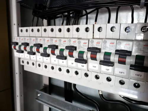
According to NEC 690.9, every ungrounded conductor originating from a power source must be protected by an overcurrent protection device (fuse or DC-rated circuit breaker). In a multi-controller installation, you must install an independent fuse or breaker between each controller’s positive output and the positive busbar:
For example, a 40A MPPT requires a minimum 40A × 1.25 = 50A DC-rated fuse (such as an MRBF terminal fuse or MIDI fuse). Never combine the outputs of two 40A controllers into a single 100A fuse; a catastrophic internal short circuit inside one controller could draw fault current from the other controller and the battery bank without tripping the oversized fuse!
4. Solving the “Premature Float” Synchronization Dilemma
The single most frustrating issue off-grid homeowners encounter when running dual charge controllers without digital communication is charging stage mismatch. Multi-stage charging follows three distinct regimes:
- Bulk Stage (Constant Current): Controllers deliver 100% available solar harvest; battery voltage climbs steadily from resting voltage up to Absorption target.
- Absorption Stage (Constant Voltage): Battery voltage is held strictly at target (e.g., 14.4V for LiFePO4 or 14.6V for AGM); current tapers down as electrochemical saturation occurs.
- Float Stage (Maintenance Voltage): Voltage is reduced to a lower resting threshold (e.g., 13.5V for LiFePO4 or 13.6V for AGM) to prevent electrolyte boil-off or lithium cell stress while powering idle inverter loads.
Why Uncoordinated Controllers Stumble
Because no two analog-to-digital voltage converters are 100% identical, Controller 1 might measure the busbar voltage as 14.41V, while Controller 2 reads the exact same busbar as 14.38V. Controller 1 believes the absorption cycle has timed out and drops its output down to Float voltage (13.5V). The moment Controller 1 drops to 13.5V, Controller 2 observes the busbar voltage dip slightly, remains in Bulk/Absorption, and continues pumping full current.
This is not dangerous, but it means Controller 1 has stopped contributing maximum solar harvest! You can solve this in two ways:
| Synchronization Method | Implementation Details | Pros & Cons |
|---|---|---|
| Digital Communication (VE.Smart / CAN Bus / Master-Slave) | Controllers link wirelessly via Bluetooth (Victron VE.Smart) or wired data cable (Renogy Parallel Hub / MidNite Solar Whizbang Jr). A single battery monitor broadcasts unified voltage and temperature data. | 100% Perfect Sync: Both controllers transition into Absorption and Float at the exact same millisecond. Requires controllers of the same manufacturer. |
| Manual Voltage Calibration (Non-Communicating Units) | Set Controller 1 and Controller 2 to identical custom profile parameters. Measure voltage at the controller output terminals with a calibrated digital multimeter and adjust target setpoints by 0.05V until both remain in Bulk simultaneously. | Universal Compatibility: Works across different brands and mixed MPPT/PWM hardware. Minor drift may occur during rapid cloud transients. |
5. Mixing Different Controller Types and Brands
One of the most common expansion questions is whether an installer can combine dissimilar charging equipment. Let us break down the exact technical boundaries:
Can You Mix MPPT and PWM Charge Controllers on the Same Battery?
Yes. As long as both controllers are configured for the exact same battery chemistry and nominal system voltage (e.g., both set to 12V LiFePO4), you can run an MPPT on your primary roof array and an inexpensive PWM on a secondary portable solar suitcase. The MPPT will harvest maximum efficiency from the high-voltage roof panels, while the PWM handles the portable array. Both will output parallel DC current to the common busbar safely.
Can You Mix Different Nominal System Voltages?
ABSOLUTELY NOT. You cannot connect a 24V charge controller and a 12V charge controller to the same battery bank. The battery bank itself dictates the nominal operating voltage of the entire DC bus. Connecting a 24V charging output across a 12V battery bank will instantly trigger severe battery overvoltage, electrolyte boiling, thermal runaway, or catastrophic BMS destruction.
- Step 1: Audit Total Continuous Charge Amperage: Verify that Controller 1 Amps + Controller 2 Amps ≤ Manufacturer Recommended Continuous Charge Current of the battery bank (LiFePO4 standard ≤ 0.5C).
- Step 2: Inspect Photovoltaic Galvanic Separation: Confirm with an ohmmeter that PV1 positive/negative circuits share zero continuity with PV2 positive/negative circuits. Solar arrays must be 100% electrically independent.
- Step 3: Program Matching Voltage Setpoints: Enter user-defined custom parameters on both units. Align Absorption Voltage, Float Voltage, and Equalization (set to 0V/Disabled for Lithium) to identical numerical values.
- Step 4: Verify Dedicated Branch OCPD Fuses: Ensure each controller has an independent, DC-rated fuse sized at 125% of its rated output current installed between the controller positive output and the positive busbar.
- Step 5: Execute Sequential Battery-First Connection: Close the battery breakers/fuses FIRST. Both charge controllers must detect battery nominal system voltage (12V, 24V, or 48V) before solar panel voltage is introduced.
- Step 6: Energize Solar PV Disconnects Sequentially: Close the DC PV disconnect for Controller 1, verify MPPT sweep lock, then close the DC PV disconnect for Controller 2. Confirm both display active bulk charging icons.
- Step 7: Conduct DC Clamp-Meter Load Verification: Place a calibrated DC clamp meter over the positive output conductor of Controller 1, then Controller 2. Verify that both are actively contributing current toward the battery bank and loads.
6. Frequently Asked Questions (PAA Search Schema)
Can two charge controllers share the same battery temperature sensor?
Generally, no. Standard analog negative temperature coefficient (NTC) temperature probes cannot be wired in parallel to two controllers, because paralleling the thermistors halves their electrical resistance, causing both controllers to register a falsely elevated temperature reading. However, modern smart ecosystems (such as Victron Energy’s VE.Smart Networking) allow a single wireless Smart Battery Sense probe to broadcast temperature and voltage data via Bluetooth to up to 10 controllers simultaneously.
Do multiple charge controllers double my battery charging time?
No, they cut charging time in half! Assuming your battery bank has the capacity to accept the combined current, adding a second charge controller of equal capacity doubles the total solar amperage flowing into the battery bank, cutting the Bulk charging duration roughly in half under full sun.
Can I connect two charge controllers directly to a lithium battery BMS?
Yes, provided you land their outputs on a common busbar that connects to the single battery bank. The BMS monitors the entire battery pack internally. It does not matter to the BMS whether 60 Amps enters from a single 60A controller or from two 30A controllers; the BMS only measures total net incoming current across its internal shunt.
What happens if one charge controller is shaded and the other is in full sun?
Nothing bad happens. The controller connected to the shaded array will drop its current output according to the reduced solar irradiance, or drop into standby mode. The controller connected to the unshaded array will continue generating full rated power without interruption.
Can I connect a wind turbine charge controller and a solar charge controller together?
Yes. Hybrid off-grid systems commonly wire a wind turbine charge controller (with an integrated dump load resistor) in parallel with a solar MPPT controller to the same battery busbar. Both act as independent charging sources.
Can I use two different brands of MPPT charge controllers together?
Yes. Different brands (e.g., a Renogy Rover and an EPEVER Tracer) can operate on the same battery bank. You must manually program both to the exact same Absorption and Float voltages using custom user profiles to ensure they transition through charging stages as closely as possible.
7. Temperature Compensation Coordination & Thermal Runaway Protection
When operating dual charge controllers on a common battery bank, temperature sensing coordination is a critical engineering requirement. During high-current charging, internal cell resistance (Rinternal) converts a portion of current into heat following Joule’s Law (P = I2R). In lead-acid (FLA/AGM/Gel) battery chemistry, failing to coordinate temperature compensation coefficients (typically -3mV/°C/cell to -5mV/°C/cell) can induce fatal thermal runaway.
If Controller 1 features an external temperature probe mounted to a center cell terminal while Controller 2 relies on an internal ambient sensor inside an unventilated electronics cabinet, a severe control divergence occurs. When the battery bank warms to 35°C (95°F) under heavy bulk current, Controller 1 safely rolls back its absorption setpoint from 14.4V to 14.1V. However, if Controller 2’s ambient sensor still reads 20°C (68°F), Controller 2 continues holding 14.5V, forcefully overcharging the hot cells and completely nullifying Controller 1’s safety reduction.
To prevent this unsynchronized charging hazard, implement one of two approved field protocols:
- Independent Physical Sensors: For unnetworked controllers, install two identical manufacturer-specific temperature sensor probes from both controllers onto adjacent terminal posts in the center of the battery pack. Never splice or parallel two analog NTC thermistor probes into a single sensor port, as paralleling halves electrical resistance and creates false high-temperature lockout faults.
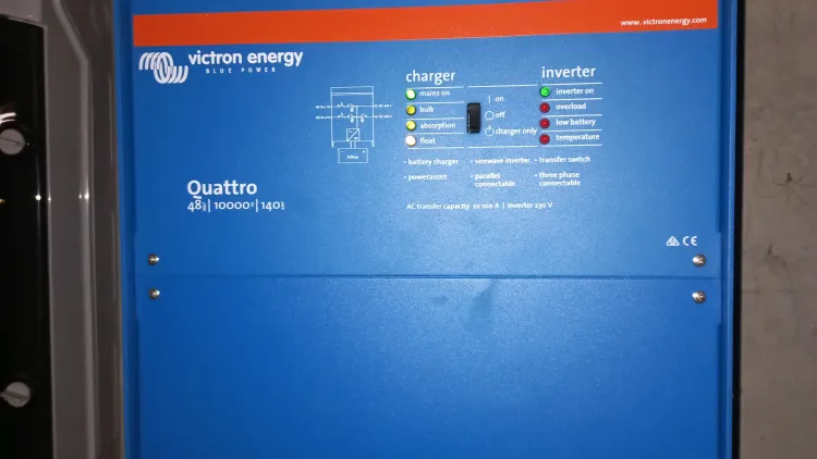
- Synchronized Digital Network Broadcast: For modern smart controllers (such as Victron SmartSolar MPPTs), deploy a unified wireless sensor (such as the Victron Smart Battery Sense or BMV-712/SmartShunt with temperature probe) over a synchronized local network (VE.Smart Networking). This enables a single calibrated reference point to broadcast real-time terminal voltage and core electrolyte temperature to all paralleled MPPT units simultaneously, guaranteeing 0.01V synchronization.