When comparing ac coupled vs dc coupled off grid architectures, DC coupling routes solar directly through an MPPT controller to batteries with 88%–93% round-trip efficiency, ideal for nighttime storage. AC coupling powers daytime AC loads at 96% efficiency, but requires a bidirectional battery inverter adhering to the 1:1 sizing rule and frequency-watt power throttling to prevent overcharging.
When designing an off-grid electrical system, choosing between alternating-current (AC) and direct-current (DC) solar coupling dictates daily conversion efficiency, long-distance transmission costs, battery life, and system survivability when batteries discharge completely. While grid-tied residential systems rely heavily on AC solar branch circuits, isolating those same components from a central electrical grid imposes rigorous physical constraints.
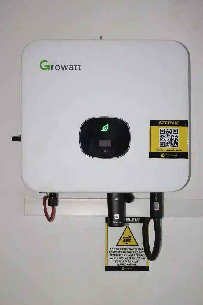
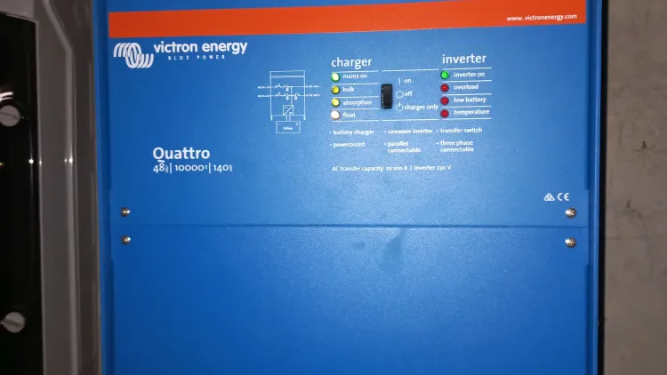
Under utility blackouts or in off-grid setups, grid-tied string inverters and microinverters cannot produce power autonomously; they lack an internal voltage reference and cannot establish an islanded AC waveform. Operating an AC-coupled microgrid requires a robust bidirectional battery inverter (such as a Victron MultiPlus, SMA Sunny Island, or Schneider Conext) to synthesize a 60 Hz reference grid while dynamically throttling solar production via frequency shifting.
1. Energy Flow Architecture: DC-Coupled vs. AC-Coupled Topologies
The fundamental distinction between DC and AC coupling lies in where photovoltaic solar power enters the system relative to the central energy storage bank:
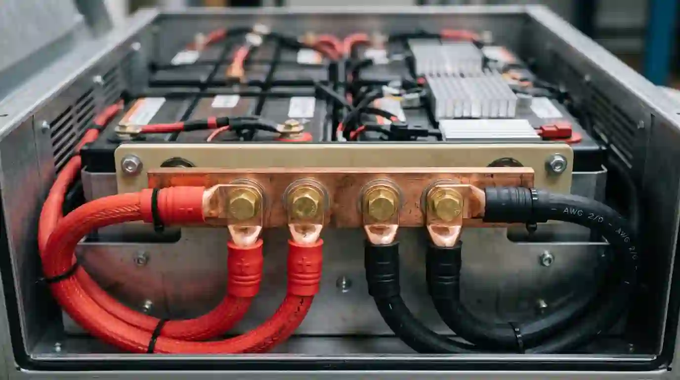
- DC-Coupled Architecture (PV → MPPT → DC Bus → Inverter → AC Loads): Photovoltaic strings connect directly to Maximum Power Point Tracking (MPPT) charge controllers. The MPPT steps high array DC voltage down to nominal battery voltage (12V, 24V, or 48V DC) on a shared common busbar. Stored DC energy is converted to 120V/240V AC power by a standalone inverter only when requested by household appliances.
- AC-Coupled Architecture (PV → Grid-Tied Inverter → AC Critical Panel → Battery Inverter → DC Battery): Photovoltaic modules connect directly to grid-tied string inverters or microinverters, converting solar DC power directly into 240V AC at the array. This AC power feeds directly into the main AC distribution panel to power active daytime loads. Any surplus AC power flows backwards through the bidirectional battery inverter charger to recharge the battery bank.
2. The Conversion Physics & Round-Trip Efficiency Loss Budget
Every power conversion stage introduces Joulean and switching semiconductor losses. According to extensive microgrid testing conducted by Sandia National Laboratories (SAND2013-5131) and the National Renewable Energy Laboratory (NREL / DOE Energy Storage Guidelines), calculating cumulative system loss requires mapping the complete power path:
The DC-Coupled Round-Trip Loss Budget:
- MPPT Buck Conversion Efficiency: ηMPPT ≈ 98.0%
- LiFePO4 Electrochemical Coulombic Efficiency: ηbattery ≈ 96.0%
- DC-to-AC Inverter Conversion Efficiency: ηinverter ≈ 93.0%
ηDC_roundtrip = 0.98 × 0.96 × 0.93 = 87.5% Cumulative Storage Efficiency
The AC-Coupled Triple Conversion Storage Penalty: When solar power is stored in batteries in an AC-coupled system, the energy undergoes three sequential conversions:
- Stage 1: PV DC to Grid-Tied AC: ηPV_inv ≈ 96.5%
- Stage 2: AC to Battery DC Charging (Battery Inverter Charger): ηcharger ≈ 93.5%
- Stage 3: LiFePO4 Electrochemical Efficiency: ηbattery ≈ 96.0%
- Stage 4: Battery DC back to AC for Household Consumption: ηinverter ≈ 93.0%
ηAC_roundtrip = 0.965 × 0.935 × 0.96 × 0.93 = 80.1% Cumulative Storage Efficiency
This 7.4% cumulative efficiency penalty means that for every 10 kWh of solar energy routed through batteries, AC coupling loses nearly 1 kWh more than DC coupling. However, for loads operating directly during peak daylight hours (e.g., well pumps, machine shops, HVAC air conditioning), AC coupling bypasses the battery entirely, achieving a stellar 96.5% direct solar-to-load efficiency.

3. The 1:1 Inverter Sizing Rule: Dynamics of Sudden Load Disconnects
The single most critical engineering requirement in an AC-coupled microgrid is the 1:1 Inverter Sizing Rule (also codified by Victron Energy as the “Factor 1.0 Rule” and by SMA as the AC-coupling guideline):
Pbattery_inverter_continuous ≥ PPV_inverter_peak_AC
Where Pbattery_inverter_continuous is the rated continuous output of the battery inverter charger (at 25°C), and PPV_inverter_peak_AC is the total nameplate AC output of all connected grid-tied PV inverters. For example, if you install a 5 kW Fronius Primo or Enphase array, your battery inverter must be rated for at least 5.0 kVA (or 5,000 watts continuous).
⚠ CRITICAL DANGER: Why Violating the 1:1 Ratio Collapses the Microgrid
Consider an off-grid homestead where an 8 kW AC-coupled solar array is powering a 6 kW water heater through an undersized 4 kW battery inverter. Suddenly, the water heater thermostat clicks off. The 6 kW load vanishes instantaneously (in zero milliseconds).
By the law of conservation of energy, the 8 kW of active solar power cannot simply disappear into thin air. It rushes backward into the battery inverter’s AC output terminals. Although the battery inverter attempts to raise frequency to throttle the solar inverters, frequency shifting requires 500 to 2,000 milliseconds for grid-tied inverters to curtail power.
Because the battery inverter is only rated to absorb 4 kW into its DC battery charger, the incoming 8 kW surge instantly overcharges the DC bus. Within milliseconds, DC bus voltage exceeds safe limits, triggering an emergency overvoltage shutdown. The microgrid collapses, plunging the home into darkness. Adhering to the 1:1 rule guarantees the battery inverter has enough continuous charger capacity to absorb full solar generation under sudden load disconnection.
4. Minimum Battery Capacity & Charge Acceptance Calculations
A compliant 1:1 inverter ratio is only half the engineering equation. The connected battery bank must also possess sufficient capacity to accept full surplus solar current without tripping its Battery Management System (BMS) on cell overvoltage.
Under Victron Energy specifications, the minimum battery bank capacity for AC coupling must provide at least 1.5 kWh of LiFePO4 storage per 1 kWp of installed AC-coupled PV (or 5.0 kWh per 1 kWp for lead-acid):
Cmin_LiFePO4 (kWh) ≥ PPV (kW) × 1.5
Furthermore, the maximum charge current must not exceed the battery’s recommended continuous C-rate. While Grade-A LiFePO4 cells tolerate 0.5C charging, lead-acid banks are capped at 0.2C. For a 5 kW PV array on a 48V (51.2V nominal) system, maximum prospective charging current reaches:
Icharge_max = 5,000 W ÷ 51.2 V = 97.6 Amperes DC
At a 0.5C charge rate, this requires a minimum lithium battery capacity of 200 Ah at 48V (10.24 kWh) to safely accept full array output without overcharging.

5. Frequency Shifting Mechanics: How Battery Inverters Throttle AC Solar
Because an off-grid microgrid cannot export power to an external electric utility, it must actively modulate solar output as batteries fill. This is achieved via Frequency-Watt Droop Control (codified under IEEE 1547-2018 Clause 5.4.2 and California Rule 21).
When the battery bank approaches its absorption target (typically 14.2V for 12V or 56.8V for 48V LiFePO4), the battery inverter begins deliberately ramping its AC output frequency upward from standard 60.00 Hz:
- 60.00 Hz to 60.20 Hz (Deadband): Inverters operate at 100% full unthrottled solar power.
- 60.20 Hz (Curtailment Start): Grid-tied inverters detect frequency rising and begin proportional linear power throttling.
- 61.00 Hz (Midpoint): Grid-tied inverters deliver exactly 50% of nameplate power.
- 62.00 Hz (Zero-Power Cutoff): Grid-tied inverters throttle power down to exactly 0% while remaining synchronized to the microgrid.
- 62.50 Hz (Emergency Hard Trip): If microgrid frequency continues climbing, grid-tied inverters physically disconnect.
💡 ENGINEERING PRO-TIP: Avoid Legacy “Hard-Trip” Inverter Profiles
Never leave grid-tied inverters on generic utility grid profiles when pairing with off-grid battery inverters. Legacy profiles treat any frequency above 60.5 Hz as an abnormal utility fault and trip the inverter completely offline (0% output) within 160 milliseconds.
This binary on/off behavior causes violent microgrid hunting: solar drops to 0%, the battery inverter pulls frequency back to 60.0 Hz, the solar inverter waits 5 minutes before reconnecting at 100% power, and the cycle repeats endlessly, causing flickering household LED lights and premature relay wear. Always select a dedicated “Microgrid Frequency-Watt” or “Rule 21” grid profile in Enphase Installer Tool, Fronius Solar.start, or SMA Sunny Design.
6. The Black-Start Vulnerability: Why AC-Coupled Solar Shuts Down on Dead Batteries
The most significant operational risk of a pure AC-coupled off-grid system is the Black-Start Lockup. If consecutive cloudy winter days drain the battery bank below its low-voltage cutoff, the battery inverter’s protective relays open, cutting AC power to the distribution panel.
When the sun rises bright and clear the following morning, the grid-tied PV inverters receive full sunlight on their panels—yet they cannot produce a single watt of power! Because the battery inverter is shut down, there is no AC voltage waveform on the panel. The grid-tied inverters remain completely dormant, and the microgrid cannot recover without an external fossil-fuel generator or portable battery charger to reboot the battery inverter.
The Hybrid Engineering Solution: To prevent black-start lockup, experienced microgrid designers deploy a Hybrid Coupling Architecture: 70% to 80% of solar capacity is AC-coupled for efficient daytime appliance operation, while 20% to 30% is DC-coupled through a dedicated MPPT charge controller directly to the battery bank. If the batteries drain completely, the DC-coupled panels recharge the battery bank autonomously the moment the sun appears, automatically bringing the battery inverter back online to restart the AC-coupled array.
Direct Amazon Link
Building a resilient AC-coupled microgrid requires a heavy-duty bidirectional battery inverter with frequency-watt curtailment, paired with a dedicated DC MPPT charge controller to guarantee black-start recovery:
The industry benchmark bidirectional battery inverter for off-grid AC coupling. Features programmable "PV Inverter Support" frequency shifting assistant, 35A high-efficiency lithium charger, and seamless transfer switching.
B0851Y5Z5J • 48V DC • 3000VA Continuous • Frequency-Watt CompatibleView Victron MultiPlus-II on Amazon →
The essential black-start safeguard for AC-coupled microgrids. Connects directly to dedicated DC PV strings to recharge depleted lithium banks from 0V without requiring an energized AC bus or external generator.
B075NQQRPD • 150V Max PV • 35A Continuous • Black-Start NativeView Victron SmartSolar MPPT on Amazon →
7. The 120% Busbar Rule (NEC 705.12(B)) in AC-Coupled Subpanels
In an AC-coupled system, the subpanel busbar is simultaneously fed by two distinct electrical sources: the off-grid battery inverter and the grid-tied PV inverters. To prevent thermal overheating and busbar failure, electrical installations must strictly comply with NEC Article 705.12(B) (The 120% Busbar Rule).
The sum of the overcurrent protection devices feeding the busbar must not exceed 120% of the busbar's continuous ampacity rating:
Imain_breaker + IPV_breaker ≤ 1.20 × Ibusbar_rating
For example, in a standard 125A distribution subpanel with a 100A main feed from the battery inverter:
Maximum Solar Breaker = (125A × 1.20) − 100A = 150A − 100A = 50A Maximum PV Breaker
Furthermore, NEC 705.12(B)(3) requires that the solar breaker be positioned at the opposite end of the busbar from the battery inverter feed, allowing currents to distribute across the busbar rather than concentrating at one terminal point. To verify breaker trip curves and ampere interrupting capacities, cross-reference our solar circuit breaker sizing guide and battery busbar sizing guide.
Follow this systematic commissioning protocol prior to placing any AC-coupled microgrid into active service:
- Step 1: Audit 1:1 Inverter Ratio & Battery Capacity: Verify that battery inverter continuous power equals or exceeds total PV inverter nameplate AC rating, and confirm battery capacity meets the 1.5 kWh per 1 kWp lithium floor.
- Step 2: Program Microgrid Grid Profile: Connect to PV inverters (Enphase Envoy, Fronius Solar.start, SMA Sunny Explorer) and select "Microgrid 60 Hz" or "Frequency-Watt Rule 21" profile to prevent binary 60.5 Hz hard trips.
- Step 3: Calibrate Battery Inverter Frequency Droop Curve: In the battery inverter software (e.g., Victron VEConfigure PV-Inverter Support Assistant), set Start Frequency to 60.20 Hz and Cutoff Frequency to 62.00 Hz.
- Step 4: Verify 120% Busbar Overcurrent Compliance: Audit the critical loads subpanel to verify that main breaker plus solar backfeed breaker do not exceed 120% of busbar rating per NEC 705.12(B).
- Step 5: Execute 100% Load-Shedding Transient Test: Power on a 3 kW resistive load (space heater or water heater element) under full midday solar production, then trip the load breaker instantly. Confirm that the battery inverter raises frequency smoothly and absorbs surplus current without triggering a DC bus overvoltage trip.
- Step 6: Verify Zero-Export Solar Curtailment: Disconnect all household loads and allow the battery to reach 100% state of charge. Verify that the battery inverter ramps microgrid frequency to 62.00 Hz and solar generation drops smoothly to exactly 0 watts.
Frequently Asked Questions
Can I add battery storage to an existing grid-tied solar system using AC coupling?
Yes. AC coupling is the ideal retrofit method because you do not need to rewire existing rooftop solar panels or replace string inverters. You simply install a bidirectional battery inverter charger between your existing solar subpanel and a new critical loads panel, ensuring the 1:1 sizing rule is met.
Why does AC coupling suffer higher efficiency losses when charging batteries?
To charge a battery bank in an AC-coupled system, electricity undergoes three separate conversions: solar DC is converted to AC by the PV inverter, converted back to DC by the battery charger, and then converted to AC again when household loads run at night. Each stage loses 4% to 7% of energy in heat.
What happens if my battery inverter is smaller than my solar array (violating 1:1 rule)?
If daytime loads suddenly shut off, surplus solar power surges backward into the battery inverter faster than frequency shifting can ramp down solar output. The excess power overcharges the internal DC bus within milliseconds, triggering an overvoltage emergency trip that crashes the entire off-grid system.
How does a hybrid-coupled system solve the black-start lockup problem?
By connecting 20% to 30% of your solar panels to a dedicated DC MPPT charge controller, those panels charge the battery bank directly whenever the sun shines—even if the battery inverter is shut down. Once battery voltage recovers, the battery inverter boots up and establishes the AC grid to restart the remaining AC-coupled solar panels.
Can standard AC household appliances be harmed by frequency shifting up to 62 Hz?
Most modern electronics, switched-mode power supplies, and inverter-driven compressors tolerate 50 Hz to 65 Hz with zero issues. However, older synchronous motor clocks or legacy washing machines may run slightly fast during peak frequency curtailment.
Mandatory Safety & Electrical Code Notice: Off-grid microgrids and bidirectional power systems involve high prospective fault currents and interconnected generation hazards. All wiring, interlocks, and overcurrent protection must comply with the local Authority Having Jurisdiction (AHJ), NEC Article 705, NEC Article 706, and IEEE 1547. Always consult a certified master electrician or professional solar engineer prior to commissioning.