Quick Answer: Correct solar battery busbar sizing requires a minimum cross-sectional area of 1.2 to 1.5 mm² per continuous DC ampere for pure copper (C11000 ETP). For a 200A continuous inverter draw, use at least a 20mm × 4mm (80 mm²) or 25mm × 4mm (100 mm²) copper bar, torqued strictly to 4.5 to 5.5 N·m (40–48 in-lbs) on M6 battery terminals.
Across off-grid electrical forums and lithium battery warranty claims, one of the most destructive yet preventable installation failures stems from improper solar battery busbar sizing and incorrect mechanical bolt torquing. When assembling a 12V, 24V, or 48V DIY battery bank using prismatic Lithium Iron Phosphate (LiFePO4) cells (such as Eve 280Ah or CATL 304Ah), builders frequently treat busbars as simple metal links. They install whatever thin copper strips shipped in the cardboard box, tighten terminal bolts by hand feel with an uncalibrated ratchet, and assume their battery interconnects are secure.
In high-current direct-current electrical engineering, busbars are high-density conductors operating under severe thermal and mechanical stresses. Pulling a continuous 2,000-watt to 3,000-watt load from a 12V or 24V battery bank demands between 100 and 250 continuous DC amperes. If your busbar cross-sectional area is undersized, Joulean heating (I2R) elevates terminal temperatures above 70°C (158°F), softening internal terminal gaskets, tripping Battery Management System (BMS) thermal sensors, and melting cable insulation. In parallel, because prismatic cells physically expand and contract during charge and discharge cycles, rigid solid bars transfer severe mechanical shearing forces into delicate laser-welded terminal studs, causing cracked seals and catastrophic internal cell degradation.
Thesis: This balance-of-system engineering guide delivers the exact cross-sectional ampacity formulas, DIN 43671 thermal dissipation standards, copper versus aluminum conductivity metrics, and calibrated torque specifications required to execute code-compliant, zero-resistance solar battery busbar sizing.
1. The Governing Physics: Calculating Busbar Ampacity & Cross-Section
Unlike round stranded electrical cables where current rating is dictated by circular mil area and insulation thermal class (e.g., 90°C THHN or 105°C fine-strand marine wire), a rectangular busbar dissipates heat entirely through surface convection and radiation. As established by John Wiles in Sandia National Laboratories’ Photovoltaic Power Systems and the National Electrical Code: Suggested Practices (OSTI ID: 808812), all conductors and busbars connecting battery banks to inverters must be sized to carry at least 125% of the continuous rated maximum current (NEC Article 690.8 and Article 706) prior to applying any temperature or enclosure derating factors. The governing thermal standard in power engineering is defined by German standard DIN 43671 (Calculation of Busbar Ampacity for Copper), which establishes continuous current carrying capacity based on allowable temperature rise over ambient air:
Design Rule: Icontinuous ≤ A (mm²) × Jallowable (A/mm²)
Where the operational variables represent:
- A (mm²): Total cross-sectional area of the conductive metal strip.
- Jallowable: Current density limit under natural air convection. In open air, copper carries roughly 1.8 to 2.0 A/mm². However, inside a sealed, unventilated battery box, industry best practice mandates derating current density to 1.2 to 1.4 A/mm² to prevent ambient thermal runaway.
- Allowable Temperature Rise (ΔT): Standard engineering designs target a maximum 30°C (54°F) rise above a 35°C ambient baseline, keeping steady-state busbar temperature below 65°C (149°F).

2. Copper vs. Aluminum: Electrical & Mechanical Comparison
When selecting raw stock for solar battery busbar sizing, builders routinely evaluate pure copper against aluminum. According to the U.S. Department of Defense Unified Facilities Criteria (UFC 3-440-01: Facility-Scale Renewable Energy Systems), pure electrolytic copper busbars with anti-corrosive electro-tin plating are strictly mandated for critical renewable microgrids to prevent galvanic degradation and ensure long-term interfacial electrical stability. While aluminum is significantly cheaper and lighter, direct-current battery banks impose physical demands where copper remains the undisputed engineering benchmark:
| Physical & Electrical Property | C11000 ETP Copper | 6061-T6 Aluminum Alloy | Engineering Impact on Battery Banks |
|---|---|---|---|
| Electrical Conductivity (% IACS) | 100.0% – 101.5% | 56.0% – 58.0% | Aluminum requires 1.6× the cross-sectional area to carry equal current. |
| Resistivity (Ω·m at 20°C) | 1.724 × 10⁻⁸ | 2.820 × 10⁻⁸ | Lower resistance means minimal voltage drop across inter-cell links. |
| Thermal Conductivity (W/m·K) | 388 W/m·K | 167 W/m·K | Copper draws heat out of internal cell terminals over twice as fast. |
| Galvanic Oxidation Behavior | Forms copper oxide (semi-conductive) | Forms aluminum oxide (insulating dielectric) | Aluminum oxide forms an electrical insulator within seconds, causing hot spots. |
| Creep Resistance (Mechanical Cold Flow) | High stability under compression | Low; relaxes under continuous pressure | Aluminum busbar bolts loosen spontaneously over time without Belleville washers. |
Engineering Verdict: For battery cell interconnects, always specify C11000 Electrolytic Tough Pitch (ETP) or C10200 Oxygen-Free (OF) copper. If budget aluminum is used on primary inverter distribution blocks, you must apply calibrated Belleville spring washers and a certified anti-galling oxide inhibitor (such as Sanchem NO-OX-ID A-Special or Ideal Noalox).
3. Archetype 12 Master Specification Matrix (BOS BOM Sizing Table)
In accordance with Archetype 12 (Bill of Materials & Balance-of-System Architecture), the comprehensive specification registry below cross-references commercial rectangular bar dimensions, continuous DC ampacity ratings, cross-sectional areas, and calibrated mechanical torque ratings:
| Dimensions (W × T) | Imperial Nominal | Area (mm²) | Area (kcmil) | Continuous DC Ampacity (ΔT 30°C) | Enclosed Box Ampacity (Derated) | Terminal Bolt Size | Torque Spec (in-lbs / N·m) |
|---|---|---|---|---|---|---|---|
| 15 mm × 2 mm | 0.60″ × 0.08″ | 30 mm² | 59.2 kcmil | 55 Amperes | 44 Amperes | M4 / M5 | 25 in-lbs (2.8 N·m) |
| 20 mm × 3 mm | 0.78″ × 0.12″ | 60 mm² | 118.4 kcmil | 110 Amperes | 88 Amperes | M6 Stud | 44 in-lbs (5.0 N·m) |
| 20 mm × 4 mm | 0.78″ × 0.16″ | 80 mm² | 157.9 kcmil | 145 Amperes | 116 Amperes | M6 Stud | 44 in-lbs (5.0 N·m) |
| 25 mm × 3 mm | 1.00″ × 0.12″ | 75 mm² | 148.0 kcmil | 140 Amperes | 112 Amperes | M6 / M8 | 44 / 75 in-lbs |
| 25 mm × 4 mm | 1.00″ × 0.16″ | 100 mm² | 197.4 kcmil | 185 Amperes | 148 Amperes | M6 / M8 | 44 / 75 in-lbs |
| 30 mm × 5 mm | 1.18″ × 0.20″ | 150 mm² | 296.0 kcmil | 265 Amperes | 212 Amperes | M8 / M10 | 75 / 130 in-lbs |
| 40 mm × 5 mm | 1.57″ × 0.20″ | 200 mm² | 394.7 kcmil | 340 Amperes | 272 Amperes | M8 / M10 | 75 / 130 in-lbs |
| 50 mm × 6 mm | 2.00″ × 0.24″ | 300 mm² | 592.1 kcmil | 480 Amperes | 384 Amperes | M10 / M12 | 130 / 220 in-lbs |
4. Interactive Solar Battery Busbar Sizing Calculator
Input your system’s maximum continuous DC current, conductor material, ambient environment, and terminal stud dimensions to calculate recommended busbar width, thickness, cross-sectional area, and calibrated torque settings for your solar battery busbar sizing project:
⚡ Solar Battery Busbar Engineering Engine
Calibrated to DIN 43671 thermal dissipation standards and NEC 110.14 mechanical torque limits.
(e.g., 200A for 2000W @ 12V or 5000W @ 24V)
152 mm²
299,976 kcmil
30 mm × 5 mm (150 mm²)
40 – 48 in-lbs
(4.5 – 5.5 N·m)
4.5 W / meter

5. Solid vs. Flexible Laminated Busbars: The Thermal Expansion Trap
One of the most insidious failure modes documented in DIY lithium battery builds is mechanical terminal sheared welds. Prismatic lithium iron phosphate cells are encased in thin aluminum cans that naturally expand and contract (often referred to in battery engineering as cell “breathing”) during repetitive charge and discharge cycles.
A typical 16-cell 48V battery bank compressed at the recommended 300 kgf (roughly 10–12 psi) expands between 0.8 mm and 2.5 mm across its cumulative length as state of charge transitions from 10% to 100%. If you install completely rigid solid copper bars across all cells:
- Shearing Force on Laser Welds: The solid copper bar does not yield. As cells expand laterally, the rigid bar acts as a mechanical lever, transferring hundreds of pounds of lateral shear force directly into the M6 or M8 terminal post.
- Terminal Seal Rupture: This continuous mechanical fatigue fractures the delicate plastic dielectric seal beneath the terminal post, venting electrolyte vapor and allowing ambient moisture to enter the cell casing.
- Stripped Thread Failure: When tightening rigid bars across mismatched terminal heights, builders frequently cross-thread or over-torque studs, stripping the soft internal aluminum threads.
Engineering Solution: Flexible Laminated Copper Busbars. Manufactured by diffusion-bonding dozens of ultra-thin (0.1 mm to 0.2 mm) electrolytic copper foil leaves with an arched or “U-shaped” expansion loop, flexible busbars absorb cell expansion seamlessly without exerting mechanical leverage on cell terminals. For high-cycle residential and mobile off-grid builds, flexible laminated busbars are mandatory.
6. Surface Preparation: Nickel Plating & Anti-Oxidant Protocols
Raw bare copper exposed to ambient atmospheric air oxidizes within hours, forming a thin, dull patina of cupric oxide (CuO) and cuprous oxide (Cu2O). While copper is an exceptional conductor, copper oxide possesses significantly higher electrical resistivity. Over thousands of operating hours under cyclic thermal loading, micro-fretting corrosion increases interface resistance across the joint.
The Golden Surface Treatment Protocol:
- Electroplated Nickel: Premium commercial busbars feature a 3 to 5 micron electroplated nickel coating. Nickel resists atmospheric oxidation, preserves mirror-flat contact surfaces, and prevents galvanic corrosion when terminating copper busbars against the native aluminum terminal pads of prismatic cells.
- Dry Contact Abrasion: If working with unplated raw copper bar stock, dress both contact faces immediately prior to assembly using 600-grit non-metallic abrasive pads (such as Scotch-Brite) soaked in 99% isopropyl alcohol. Never use steel wool or carbon emery paper, as embedded conductive iron particles promote accelerated galvanic pitting.
- Sanchem NO-OX-ID A-Special: Apply a microscopic, translucent film of conductive synthetic grease across the mating faces. Wipe away excess so that grease fills only micro-voids without accumulating on bolt threads.
7. Calibrated Torque & Thread Safety (NEC 110.14(D) Compliance)
In the 2020 and 2023 National Electrical Code, NEC Article 110.14(D) formally mandated the use of calibrated torque tools for all field electrical terminations. Tightening by “feel” with a standard box wrench is an explicit violation of electrical building codes. In off-grid battery construction, both under-torquing and over-torquing lead to catastrophic failure:
- Under-Torquing (< 3.0 N·m / 26 in-lbs): Insufficient clamping pressure allows microscopic air gaps between the busbar and terminal face. Under a 200A load, a mere 0.5 milliohm contact resistance dissipates 20 watts of concentrated heat
P = I2R = 2002 × 0.0005 Ω = 20 Win a space smaller than a postage stamp, rapidly exceeding 100°C (212°F) and melting adjacent BMS balance wires. - Over-Torquing (> 6.5 N·m / 58 in-lbs on M6): The internal female threads of Eve and CATL terminals are machined into soft aluminum alloy. Exceeding 6 N·m strips the internal threads instantly, permanently ruining an expensive 120 to 180 USD prismatic cell.
Recommended Hardware Stacking Sequence (Bottom to Top):
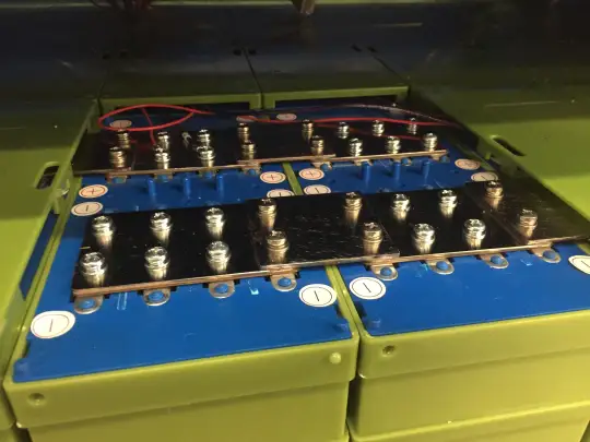
Proper Terminal Fastening Order (Direct Contact Architecture):
- Bottom Layer: Aluminum Cell Terminal Pad.
- Second Layer: Nickel-Plated Copper Busbar (Placed directly against the terminal pad for zero contact resistance).
- Third Layer: BMS Voltage Sense Ring Terminal (Placed ON TOP of the busbar, never sandwiched beneath it!).
- Fourth Layer: High-Grade Stainless Steel 304 Flat Washer.
- Fifth Layer: Stainless Steel Belleville (Conical Disc Spring) Washer (Maintains dynamic clamping pressure during thermal expansion cycles).
- Top Layer: Stainless Steel Grade A2-70 Serrated Flange Nut or Hex Bolt torqued with a calibrated inch-pound torque wrench to 4.5 – 5.0 N·m (40 – 44 in-lbs).
8. How System Voltage Dictates Solar Battery Busbar Sizing (12V vs. 24V vs. 48V)
When engineering high-power off-grid energy storage, system nominal voltage acts as the ultimate multiplier in solar battery busbar sizing. Under basic electrical power physics P = V × I, delivering identical wattage requires quadruple the amperage at 12 volts compared to 48 volts. Consequently, conductor cross-sectional requirements scale dramatically:
- 12V Battery Architecture (3,000W Inverter Load): Pulls up to 280 to 300 continuous DC amperes. Requires heavy 40mm × 5mm (200 mm²) copper bar stock to prevent terminal temperatures exceeding 60°C. Joulean I2R resistive heating is severe.
- 24V Battery Architecture (3,000W Inverter Load): Pulls 140 to 150 DC amperes. Sizing drops comfortably to a compact 25mm × 3mm (75 mm²) copper busbar, reducing copper material weight and raw hardware costs by over 60%.
- 48V Battery Architecture (3,000W Inverter Load): Pulls just 65 to 75 DC amperes. Operates effortlessly on a standard 20mm × 3mm (60 mm²) busbar with negligible thermal rise (< 10°C over ambient). Cable and terminal stress is minimized.
This stark disparity illustrates why professional off-grid builders transition to 48V topologies for any system exceeding 2,000 continuous watts: higher voltage keeps solar battery busbar sizing within manageable physical dimensions while virtually eliminating resistive Joulean thermal bottlenecks.
9. Parallel Multi-Bar Derating: Sizing Dual and Triple Busbar Stacks
In high-capacity commercial power centers or industrial 48V battery banks exceeding 400 continuous amperes, installing a single ultra-thick copper bar (e.g., 10mm or 12mm thickness) becomes physically impractical to bend and drill. In such architectures, engineers stack two or three thinner copper bars in parallel separated by air gaps.
However, when stacking multiple busbars in parallel, builders must never assume ampacity doubles linearly. As codified in DIN 43671, parallel bars restrict internal convective airflow and radiation between adjacent faces:
| Busbar Assembly Configuration | Effective Ampacity Multiplier | Required Air Gap Spacing | Engineering Application |
|---|---|---|---|
| Single Flat Bar (1x) | 1.00× (Baseline 100%) | N/A | Standard inter-cell series links (up to 250A) |
| Two Bars in Parallel (2x) | 1.65× – 1.75× (Not 2.0×!) | Equal to bar thickness (t) | Main battery combiner busbars (300A – 500A) |
| Three Bars in Parallel (3x) | 2.20× – 2.30× (Not 3.0×!) | Equal to bar thickness (t) | Industrial power centers > 600A continuous |
To achieve the rated parallel multiplier, bars must be separated using copper or brass spacer washers matching the thickness of the bar. Clamping two bars flat against one another without an air gap allows zero internal air cooling, degrading total ampacity down to barely 1.3× that of a single bar!
10. Overcurrent Protection Integration: Direct Busbar Fuse Mounting
An essential balance-of-system rule in solar battery busbar sizing is the direct physical integration of overcurrent protection. Under National Electrical Code NEC Article 706.31, all ungrounded conductors emerging from energy storage systems must be protected by an approved overcurrent protective device (OCPD) with an adequate Ampere Interrupting Capacity (AIC) rating.
Lithium battery banks possess extraordinarily low internal impedance, capable of delivering instantaneous short-circuit fault currents exceeding 10,000 to 20,000 amperes. Standard automotive glass fuses, mega-fuses, or ANL fuses will vaporize or weld their internal contacts shut into a catastrophic plasma arc. Only authentic Class T fuses (rated at 20,000A DC AIC at 125V) or high-grade Marine Rated Battery Fuses (MRBF rated at 10,000A AIC) comply with safety codes.
Rather than connecting a short length of flexible cable between the battery terminal and the fuse holder—which introduces two crimp lugs and four bolted interfaces—best practice mounts a Class T fuse block directly onto the positive terminal distribution busbar using grade A2-70 stainless steel M10 studs. This direct-mount topology eliminates intermediate conductor resistance and ensures complete short-circuit safety within seven inches of the battery supply.
11. High-Frequency Ripple & Magnetic Induction in Hybrid Inverters
While solar battery storage operates fundamentally on direct current, modern high-frequency switch-mode hybrid inverters (such as Victron MultiPlus-II, Sol-Ark, and EG4 units) generate high-frequency AC ripple currents at twice the alternating-current line frequency (120 Hz) overlaid onto the DC busbar. Under heavy inverter loads, this ripple current can reach 10% to 20% of the DC amperage.
In cylindrical conductors, alternating-current magnetic fields induce the skin effect, forcing current density toward the outer perimeter. In flat rectangular busbars, however, the high width-to-thickness aspect ratio (typically 4:1 to 6:1) maximizes surface area, naturally mitigating skin effect and high-frequency inductive eddy currents. This structural advantage confirms why rectangular copper busbars run substantially cooler and exhibit lower total impedance than equivalent gauge round stranded cables under heavy inverter switching harmonics.
12. Step-by-Step Commissioning SOP for Solar Battery Busbar Sizing
Before energizing your completed battery bank, execute this standardized six-point balance-of-system commissioning checklist. These steps align with commissioning protocols published by the National Renewable Energy Laboratory (NREL Report OSTI ID: 2583466 / 1483861) for battery energy storage systems (BESS), ensuring sub-milliohm joint integrity and preventing localized thermal runaway:
- Verify Flatness & Deburr Holes: Inspect drilled bolt holes on all copper busbars. Remove all raised metal burrs using a countersink bit to guarantee 100% planar contact across the terminal pad.
- Chemical Degreasing: Clean all contact surfaces with 99% anhydrous isopropyl alcohol to eliminate manufacturing cutting oils and finger oils.
- Apply Conductive Inhibitor: Smear a micro-layer of Sanchem NO-OX-ID A-Special across mating faces.
- Hardware Alignment: Verify that BMS balance wire ring terminals rest strictly ON TOP of the busbar, backed by flat washers and conical Belleville spring washers.
- Two-Stage Calibrated Torquing: Using an inch-pound torque wrench calibrated to NEC 110.14(D), torque all M6 bolts initially to 3.0 N·m (26 in-lbs) in sequence. Complete a second pass torquing to final specification: 4.8 N·m (42 in-lbs). Mark each bolt head with a visual torque inspection paint pen.
- Thermal Baseline Scan: Energize the system and apply a 50% inverter load for 30 minutes. Measure every busbar connection using a calibrated thermal imaging camera or infrared pyrometer. Any terminal exhibiting a temperature more than 5°C (9°F) above adjacent cells indicates high contact resistance requiring immediate re-torquing.
Every cross-sectional ampacity formula, torque limit, and plating specification in this guide is grounded in published government research laboratory standards, military unified criteria, and national electrical codes:
Engineering rules for battery interconnect ampacity, continuous current multipliers (125% per NEC 690.8/706), and Class T 20,000A AIC fuse protection.
Military specifications for heavy-duty DC copper busbars, anti-corrosive electro-tin plating, dielectric isolation, and mechanical bolt clamping integrity.
Stationary battery interconnection commissioning protocols, infrared thermographic Delta-T criteria, and LiFePO4 220°C thermal stability standards.
Guidelines for minimizing inter-cell electrical resistance, preventing localized Joulean terminal heating, and maintaining cell-to-cell balance.
Frequently Asked Questions (FAQ)
Can I make my own DIY copper busbars from copper pipe?
While possible in emergencies, flattening Type L or Type M copper plumbing pipe with a hammer or shop press creates micro-cracks, uneven contact faces, and unpredictable thickness. Plumbing copper is work-hardened and lacks the mirror-flat planar surface necessary for sub-milliohm electrical contact. Always purchase precision cold-drawn C11000 ETP flat bar stock with milled edges.
What size busbar do I need for a 3,000-watt inverter at 12V?
A 3,000-watt inverter running on a 12-volt battery bank draws up to 280 to 300 continuous DC amperes (accounting for 88% efficiency and 10.5V low-battery cutoff). To keep steady-state temperature rise below 30°C, you require a minimum busbar cross-sectional area of 150 mm² to 200 mm². We recommend a 30mm × 5mm (150 mm²) or 40mm × 5mm (200 mm²) C11000 copper busbar.
Why should I never put the BMS balance ring terminal under the busbar?
Placing a small brass or tin BMS ring terminal beneath the heavy busbar reduces the primary contact surface area by over 70%, forcing hundreds of amperes through a flimsy 0.8 mm ring lug. This creates an immediate severe electrical bottleneck, excessive resistive heating, and false BMS temperature alarms. The busbar must always mate directly against the cell terminal.
Do I need to insulate battery busbars inside a cabinet?
Yes. Per NEC Article 706 and NFPA 70E safety guidelines, uninsulated energized DC busbars present catastrophic short-circuit and arc-flash explosion hazards if a metal tool is accidentally dropped across terminals. Protect inter-cell busbars using flame-retardant clear polycarbonate (Lexan) top shield covers or slide flame-retardant silicone/polyolefin insulating sleeves over each bar.
How does ambient temperature affect solar battery busbar sizing?
Conductor electrical resistance increases linearly with temperature according to copper’s temperature coefficient (α = 0.00393 per °C). In desert climates or enclosed mobile power compartments exceeding 45°C (113°F), busbar ampacity must be derated by 15% to 20% to prevent cumulative thermal buildup from exceeding terminal gasket limits.