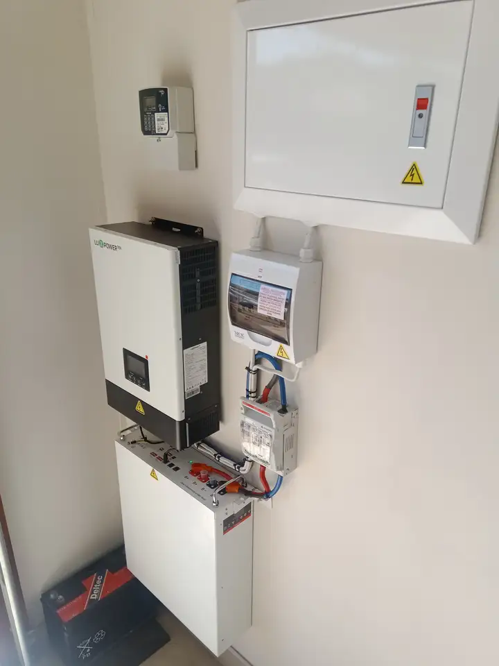
To charge an electric vehicle off-grid for an average 35-mile daily commute (~11 kWh), you need a minimum 3,200W to 4,000W solar array, an 8 kW split-phase 240V pure sine inverter, and a 15 kWh to 20 kWh 48V LiFePO4 battery bank, which you can model in our free off-grid solar system sizing calculator. Because a standard 40A Level 2 charger draws 9.6 kW continuous (exceeding most residential off-grid inverters), you must throttle charging to 16A or 24A (3.8 kW to 5.7 kW). Check our inverter sizing guide and 12V vs 24V vs 48V battery comparison to balance high-amperage vehicle charging with off-grid cabin safety.
EV owners assume plugging a standard 40A or 50A home Level 2 charger into a 5,000W or 6,000W off-grid solar inverter will charge their car seamlessly just like grid utility power.
Under NEC 625.42, a 40A charger pulls 9,600W continuously (240V × 40A), requiring a 50A branch circuit. Connecting a 9.6 kW load to a 5 kW or 6 kW off-grid inverter causes immediate thermal shutdown or BMS overcurrent trips. Successful off-grid charging requires dynamic current throttling to 16A or 24A (3.8 kW to 5.7 kW) or a true 10 kW+ split-phase inverter system.
Many off-grid inverters and portable solar power stations output a “floating neutral” where the AC neutral line is isolated from the equipment grounding conductor. Smart EV chargers (EVSEs) perform an automatic impedance handshake before closing internal contactors. If the EVSE senses an open or floating ground, it will immediately lock out with a flashing red Ground Fault error and refuse to charge. To satisfy NEC 250.30 and NEC 625, standalone off-grid inverters operating as separately derived systems must have an established neutral-to-ground bonding jumper installed at the main AC disconnect panel.
1. The Physics of Off-Grid EV Charging: Level 1 vs. Level 2
Charging an electric vehicle involves rectifying alternating current (AC) into direct current (DC) to saturate the vehicle’s high-voltage traction pack (typically 400V or 800V architecture). In an off-grid solar installation, this process introduces distinct electrical trade-offs between standard 120V convenience and high-amperage 240V split-phase charging.
| Charging Tier | Voltage & Current | Continuous Load | Recovery Rate (mi/hr) | Off-Grid Inverter Impact |
|---|---|---|---|---|
| Level 1 (Standard) | 120V @ 12A | 1.44 kW | 3 – 5 miles | Low strain; high parasitic BMS loss (18-25%) |
| Level 2 (Throttled) | 240V @ 16A | 3.84 kW | 12 – 15 miles | Sweet spot: 88-92% efficiency, low thermal stress |
| Level 2 (Mid-Rate) | 240V @ 24A | 5.76 kW | 18 – 22 miles | Requires 8 kW+ inverter; excellent solar tracking |
| Level 2 (Full Grid) | 240V @ 40A | 9.60 kW | 30 – 36 miles | Extreme: Demands 12 kW+ inverter or parallel units |
The Hidden Parasitic Penalty of 120V Level 1 Charging
While plugging into a conventional 120V wall outlet appears gentle on an off-grid inverter, it is mathematically the least efficient way to charge an electric car. An EV’s onboard computer, coolant pumps, thermal management heaters, and battery sensors draw an unavoidable 250W to 400W of parasitic power continuously whenever a charging session is active. At 1.44 kW (120V × 12A), parasitic systems consume up to 27% of the total energy, leaving barely 1.05 kW entering the battery. By stepping up to 240V split-phase charging at 16A (3.84 kW), parasitic consumption drops to under 8%, cutting solar energy waste by more than two-thirds.
2. Daily Mileage to Kilowatt-Hour Formulas: Step-by-Step Math
The cardinal rule of off-grid EV sizing is to size for daily mileage replacement rather than full battery capacity. Sizing a solar array to charge a 75 kWh to 130 kWh electric truck battery from 0% to 100% in a single day results in an absurdly oversized, multi-thousand-dollar microgrid that sits idle most of the week. Instead, calculate based on your real-world daily driving radius.
Calculate Net Daily Vehicle Energy Demand (E_vehicle)
Example: An off-grid homesteader drives a Tesla Model Y (efficiency: 3.3 mi/kWh) an average of 35 miles round-trip per day. E_vehicle = 35 ÷ 3.3 = 10.61 kWh per day.
Account for Inverter & Onboard Rectification Losses (E_ac)
Loss Parameters: Onboard EV rectification efficiency (η_charger) averages 88% to 90% at 240V. Off-grid split-phase pure sine inverter efficiency (η_inverter) averages 92% to 94%. Combining these efficiencies gives a derate factor of 0.89 × 0.93 = 0.828. E_ac = 10.61 ÷ 0.828 = 12.81 kWh/day of AC energy required from your stationary power system.
Size the 48V Stationary Storage Bank (C_battery)
Battery Parameters: Utilizing lithium iron phosphate (LiFePO4) chemistry with an 80% maximum recommended continuous Depth of Discharge (DoD = 0.80) and 95% round-trip Coulombic efficiency (η_battery = 0.95), buffering 1 full day of driving energy requires: 12.81 ÷ (0.80 × 0.95) = 16.85 kWh of 48V battery storage (~330Ah at 51.2V nominal).
Size the Dedicated Solar PV Array (P_array)
Solar Parameters: In a geographic zone averaging 4.5 Peak Sun Hours (PSH) per day, applying the standard NREL PVWatts derate factor of 0.78 (accounting for thermal cell losses, MPPT tracking inefficiency, dust/soiling, and wire voltage drop): P_array = (12.81 × 1,000) ÷ (4.5 × 0.78) = 3,650 Watts of Solar Panels (approx. nine 400W monocrystalline modules).
3. Inverter Sizing: Continuous Ratings, Surge Headroom & Split-Phase 240V
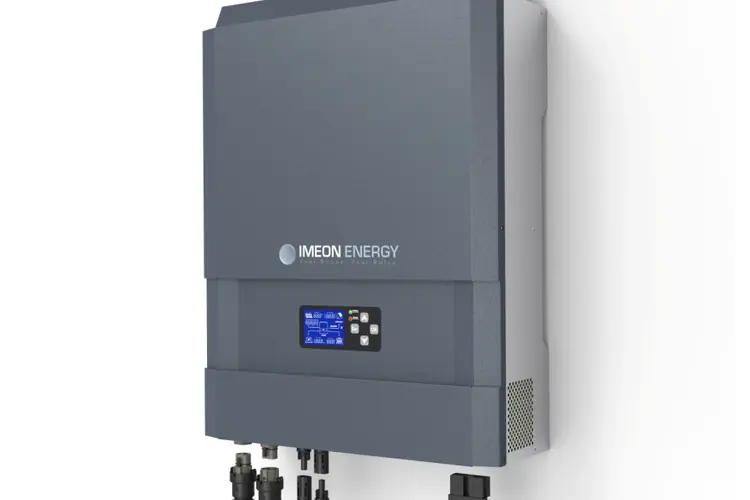
The single greatest operational bottleneck in off-grid EV charging is the inverter’s continuous wattage limit. While grid-tied homes draw limitless power from utility substations, an off-grid inverter is strictly governed by power electronics heat dissipation and transformer core saturation.
| EV Charger Continuous Amps | Continuous AC Load (240V) | NEC 625.42 Branch Circuit (125%) | Minimum Recommended Inverter Continuous Rating |
|---|---|---|---|
| 16 Amps (Throttled Level 2) | 3,840 Watts (3.84 kW) | 20A 240V Breaker (12 AWG Cu) | 5.0 kW to 6.0 kW Split-Phase |
| 24 Amps (Mid-Duty Level 2) | 5,760 Watts (5.76 kW) | 30A 240V Breaker (10 AWG Cu) | 8.0 kW Split-Phase |
| 32 Amps (High-Duty Level 2) | 7,680 Watts (7.68 kW) | 40A 240V Breaker (8 AWG Cu) | 10.0 kW to 12.0 kW Split-Phase |
| 40 Amps (Standard Level 2) | 9,600 Watts (9.60 kW) | 50A 240V Breaker (6 AWG Cu) | 15.0 kW Paralleled Split-Phase |
Why 120V Inverters Cannot Power a Standard Level 2 EVSE
A frequent DIY mistake is attempting to power a 240V NEMA 14-50 EV receptacle using two separate 120V inverters that are not phase-locked. Level 2 charging requires two 120V alternating current hot legs (L1 and L2) operating precisely 180 degrees out of phase, producing 240 volts line-to-line. Connecting unsynchronized 120V sources creates dangerous phase drift that destroys the vehicle’s onboard charger. Always specify a native 120V/240V split-phase pure sine inverter or two stackable inverters connected via a manufacturer-approved synchronization cable.
Off-Grid EV Solar Sizing & Inverter Calculator
Calculate solar array wattage, inverter continuous rating, and 48V battery capacity customized to your daily mileage and EV charging current.
Direct Amazon Purchase Links
To deploy an off-grid EV charging station that prevents inverter collapse while keeping domestic cabin power secure, specify hardware engineered for continuous duty, current adjustability, and autonomous monitoring:
Smart adjustable current throttling (16A, 24A, 32A, 40A) prevents inverter thermal overload. Features NEMA 14-50 plug, smart RFID security, smart app scheduling, and UL-compliant contactors.
Native NACS connector for direct Tesla charging without loose mechanical adapter pins. Supports up to 40A split-phase charging, IP66 waterproof enclosure, and interchangeable NEMA 14-50/5-15 plugs.
Ultra-quiet reversible brushless DC motor consuming just 35W to 45W. Distributes wood stove heat downward in winter and cools in summer, paired with an extra-large 3,545-lumen dimmable LED fixture.
Completely autonomous cellular surveillance for remote charging bays, solar arrays, and cabins without Wi-Fi. Features 940nm stealth no-glow night vision, 0.2s motion trigger, and dedicated solar collector.
4. Stationary Battery Bank Sizing: Why 48V Architecture Is Mandatory
A frequent beginner question is whether an existing 12V or 24V campervan or cabin battery system can be expanded to charge an electric car. From an electrical engineering perspective, attempting to run a Level 2 EV charger on a 12V or 24V battery architecture is fundamentally hazardous and economically unviable due to Ohm’s Law and resistive heating (I2R thermal resistive losses).
Consider the continuous DC current entering an inverter delivering 5,000 watts of continuous power to an EV at 16 amps (240V):
- 12V Battery System: 5,000W ÷ 12V = 416.7 Amps DC continuous. This demands massive 4/0 AWG parallel copper welding cables, generates severe thermal dissipation, and instantly trips standard 100A or 200A lithium BMS units.
- 24V Battery System: 5,000W ÷ 24V = 208.3 Amps DC continuous. Still requires heavy 2/0 AWG conductors and stresses modular battery connections.
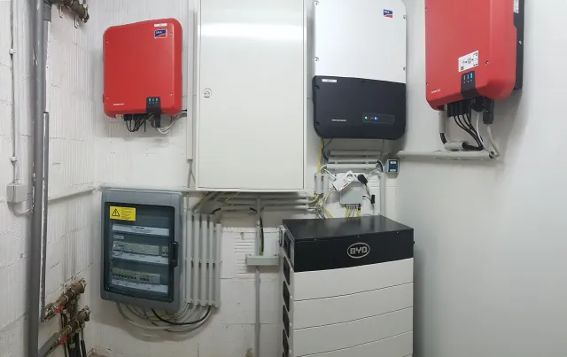
- 48V Battery System (51.2V nominal): 5,000W ÷ 51.2V = 97.6 Amps DC continuous. This brings current under 100 amps, allowing standard 2 AWG copper cabling and operating safely within the 100A continuous discharge threshold of standard server-rack LiFePO4 batteries.
SAND2016-10700 / Section 3.2
C-Rate Discharge Fatigue on Stationary Lithium Storage
Sandia National Laboratories testing documents that cycling LiFePO4 cells at continuous discharge rates exceeding 0.5C (discharging the battery in under 2 hours) accelerates internal mechanical electrode strain and increases capacity fade by up to 300% compared to a 0.2C rate. To charge an EV drawing 5 kW continuously, an off-grid 48V battery bank should possess a minimum capacity of 15 kWh to 20 kWh (300Ah to 400Ah at 48V). This ensures the continuous EV load represents a gentle 0.25C to 0.33C discharge rate, guaranteeing 4,000 to 6,000 cycles to 80% capacity retention.
5. Dynamic Amperage Throttling: Preventing Inverter Voltage Collapse
Standard municipal EV chargers are designed under the assumption of an infinite grid supply: when you plug in, the vehicle demands its maximum allowable current (typically 32A to 48A). In an off-grid environment, this uncontrolled maximum draw is fatal to inverter health. If your solar array is generating 3,000 watts at mid-day and the EV abruptly pulls 9,600 watts, the battery bank must instantaneously supply the remaining 6,600 watts.
SAE J1772 & SAE J3400 (NACS)
Control Pilot Signal Pulse-Width Modulation (PWM)
Under SAE J1772 and SAE J3400 standards, the EVSE communicates maximum available current to the vehicle using a 1 kHz square wave on the Control Pilot (CP) pin. The duty cycle of this PWM wave dictates the vehicle’s onboard rectifier limit: a 26.6% duty cycle corresponds to 16A (3.84 kW), a 40% duty cycle sets 24A (5.76 kW), and a 53.3% duty cycle allows 32A (7.68 kW). Smart off-grid chargers utilize manual or app-driven pilot modulation to lock the EV to the exact available solar generation.
By deploying a smart Level 2 EVSE with adjustable current selection (such as the WOLFBOX 40A/50A Level 2 EV Charger with smart RFID and selectable 16A, 24A, 32A, and 40A thresholds), off-grid operators can modulate charging throughout the day:
- Morning / Overcast (16 Amps): Draws 3.8 kW. Matches modest solar output and allows domestic cabin loads to run without inverter strain.
- Peak Solar Noon (24 to 32 Amps): Draws 5.7 kW to 7.6 kW directly from solar production, charging the car rapidly while minimizing battery cycling.
- Night / Storage Reserve (16 Amps): Dials down current to ensure low discharge C-rates on the 48V stationary battery bank.
6. Charging Tesla & NACS Vehicles on Off-Grid Inverters
Tesla vehicles (Model Y, Model 3, Model X, Cybertruck) and modern electric cars adopting the SAE J3400 North American Charging Standard (NACS) utilize sophisticated power monitoring algorithms that react uniquely to off-grid power quality. Understanding these behaviors prevents charging aborts and error notifications.
The 25% Automated Voltage-Sag Derate Feature
Tesla onboard rectifiers continuously monitor the root-mean-square (RMS) AC line voltage. If an undersized off-grid inverter experiences voltage sag—dropping line voltage by more than 5% (below 228V on a 240V split-phase circuit) when the vehicle initiates charging—Tesla firmware automatically reduces the charging current by 25% to protect the electrical circuit. If the voltage continues to sag below 215V, the vehicle will terminate the session and display “Charging Stopped / Line Voltage Too Low”.
To prevent automated Tesla charging aborts, ensure your 240V branch feeder from the inverter to the NEMA 14-50 receptacle uses low-resistance conductors (minimum 6 AWG copper for runs under 50 feet, or 4 AWG copper for runs exceeding 75 feet). Furthermore, utilize a dedicated NACS mobile charging unit (such as the WOLFBOX PE40T 2-in-1 Tesla Charger with native NACS handle and NEMA 14-50 plug) to eliminate loose mechanical adapter connections that cause localized resistance and thermal voltage drop.
7. Homestead Energy Budgeting: How a 35W DC Fan Protects the Battery Bank
The greatest operational danger to an off-grid solar microgrid is simultaneous high-surge household consumption occurring while the electric vehicle is drawing power. When an EV is charging at Level 2 rates (drawing 3,840W at 16A or 5,760W at 24A), an 8 kW to 10 kW off-grid inverter operates with very little remaining continuous headroom.
If a conventional 3,000-watt central air conditioner or 1,500-watt electric space heater cycles on simultaneously, the total load will immediately exceed the inverter’s maximum continuous rating. The system will either collapse into an inverter overload trip or aggressively drain the stationary 48V battery bank below safe low-voltage cutoff limits.
| Climate Control Appliance | Continuous Power Draw | 8-Hour Energy Consumption | Impact While EV Charges (16A EVSE) |
|---|---|---|---|
| Standard RV / Cabin Air Conditioner | 2,200W to 3,000W | 17,600 Wh to 24,000 Wh | Severe Overload Risk / Battery Depleted |
| Portable Electric Ceramic Heater | 1,500W Continuous | 12,000 Wh | High Thermal Strain on DC Inverter Bus |
| AUNLPB 7-Blade Solid Wood DC Ceiling Fan | 35W to 45W Continuous | 280 Wh to 360 Wh | Negligible (Less than 1% of Inverter Headroom) |
The 35W Thermal Circulation Strategy
Experienced off-grid homesteaders balance their vehicle charging energy budget by replacing power-hungry resistive cooling and heating with ultra-efficient, brushless DC motor air movers. Deploying an ultra-low-wattage ceiling fixture (such as the AUNLPB 7-Blade Solid Wood Ceiling Fan with Light) delivers two critical engineering advantages:
- Summer Cooling Without Inverter Strain: The 7-blade aerodynamic solid wood profile produces powerful convective airflow (wind chill effect), dropping effective perceived indoor room temperature by 6°F to 8°F while consuming a trivial 35 watts—roughly 1/85th the power consumption of an air conditioner.
- Winter Wood Stove Heat Destratification: In cold off-grid cabins, wood stoves cause extreme thermal stratification, trapping 85°F air near the ceiling while floors remain near 55°F. The AUNLPB fan’s reversible DC motor pushes warm ceiling air downward, distributing wood heat evenly across the living space without requiring electric resistance blowers while your EV charges overnight.
- Ultra-Bright Integrated LED Lighting: Features a high-output 3,545-lumen dimmable LED fixture, consolidating primary workshop or cabin lighting into a single energy-efficient DC load.
8. Remote Charging Station Security: Autonomous 4G Solar Surveillance
On rural acreages, mountain cabins, and off-grid homesteads, vehicle charging stations, solar arrays, and high-capacity battery sheds are frequently situated in detached garages, barns, or open carports hundreds of feet away from the main residence. Crucially, these remote outbuildings are almost universally outside the range of residential Wi-Fi networks.
An electric vehicle parked outdoors connected to a heavy-gauge copper charging cable and backed by thousands of dollars of ground-mount solar panels represents an enticing target for copper theft, unauthorized tampering, and roaming wildlife. Protecting remote charging infrastructure requires a completely autonomous, wire-free security perimeter.
Zero-Wi-Fi Remote Monitoring with 4G Solar Cameras
Deploying a dedicated cellular surveillance system (such as the Xega 4G Solar Cellular Security/Trail Camera) eliminates the vulnerability of remote off-grid charging stations:
- Zero Impact on the Cabin Battery Bank: The camera features its own integrated high-efficiency solar panel and internal lithium battery buffer. It operates completely self-sufficiently, drawing zero watts from your main 48V stationary power system.
- Independent 4G LTE Connectivity: Connects directly to cellular LTE networks via an onboard SIM card, delivering instant push notifications, live HD video streaming, and motion alerts directly to your smartphone without requiring local Wi-Fi or router power.
- 940nm No-Glow Stealth Night Vision: Unlike cheap security cameras that emit visible red infrared LEDs (revealing their location in the dark), the Xega utilizes true 940nm non-visible infrared illumination and 0.2-second rapid PIR motion detection, capturing crystal-clear nighttime footage of intruders or nocturnal wildlife in complete stealth.
9. 2026 Black Friday & Cyber Monday Hardware Clearance Audit
The annual holiday shopping corridor (November 19 through December 31) represents the premier window for off-grid homesteaders and cabin builders to acquire heavy-duty charging and electrical hardware at substantial discounts. Tier-one manufacturers offer clearance pricing, promotional coupon codes, and verified holiday bonus bundles across essential off-grid EV infrastructure.
When auditing holiday equipment promotions, follow these three engineering verification rules to ensure genuine value:
- Verify Continuous Duty ETL / UL Certification: Never purchase cheap uncertified EV chargers that lack ETL or UL 2594 listings. High-amperage continuous loads create severe fire hazards if internal relays and terminal contactors lack certified thermal testing.
- Insist on Native Amperage Adjustability: Ensure the EVSE features physical switchable or app-driven current throttling (16A, 24A, 32A, 40A) rather than fixed-rate 40A charging, guaranteeing compatibility with off-grid inverters.
- Audit Stackable Clip-On Coupons: Take advantage of verified manufacturer holiday promotional links and clip-on coupons that provide instant percentage discounts alongside seasonal clearance pricing.
10. Electrical Safety & Code Compliance: NEC 625, NEC 250 & Grounding
Installing high-amperage vehicle charging infrastructure on a standalone solar microgrid must strictly comply with National Electrical Code (NEC) standards to prevent catastrophic electrical fires, insulation breakdown, and lethal shock hazards. Because off-grid inverters operate as “Separately Derived Systems,” the following three electrical code mandates are legally and practically non-negotiable:
1. Continuous Duty Branch Sizing (NEC 625.41 & 625.42)
NEC Article 625 specifies that all EVSE branch circuits must be treated as continuous loads. The branch circuit overcurrent protection device (breaker) and conductors must be sized for at least 125% of the charger’s maximum continuous amperage rating. For a 40A charger, install a minimum 50A dual-pole circuit breaker and 6 AWG copper conductors rated for 75°C. For a 32A charger, install a 40A breaker with 8 AWG copper conductors. Never undersize conductors to match intermittent appliance charts.
2. Separately Derived Neutral-to-Ground Bonding (NEC 250.30)
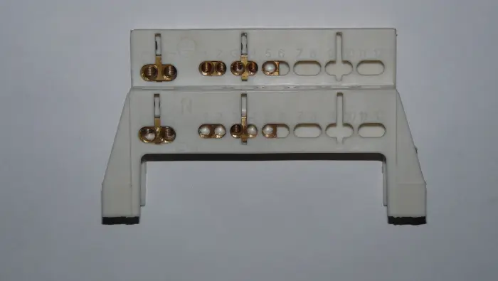
A standalone off-grid inverter that is not tied to the utility grid is classified under NEC 250.30 as a separately derived AC system. In this topology, you must establish a single, robust System Bonding Jumper (SBJ) connecting the AC Neutral bus to the Equipment Grounding Conductor (EGC) bus at the primary inverter AC disconnect or sub-panel. Without this single-point bond, the system operates with a floating neutral, preventing the EVSE’s internal ground-fault monitoring circuit from completing its safety handshake and causing solid red error lockouts.
3. Dedicated Grounding Electrode System (NEC 250.32 & NEC 250.52)
Where the vehicle charging station is located in an outbuilding or detached carport served by a feeder from the main power shed, drive a dedicated 8-foot copper-clad grounding electrode rod at the charging location. Bond this grounding electrode to the sub-panel ground busbar using a minimum 6 AWG bare copper conductor to provide lightning surge dissipation and stabilize voltage during high-current charging cycles.
11. 5 Critical DIY Off-Grid EV Charging Mistakes to Avoid
- Attempting 40A Charging on an Undersized 6 kW to 8 kW Inverter: Standard 40A home chargers draw 9.6 kW continuous. Connecting this to an 8 kW inverter causes rapid thermal trip shutdowns. Always deploy a smart charger with native 16A or 24A current throttling (such as the WOLFBOX 40A/50A Level 2 EV Charger) to match inverter continuous output.
- Ignoring the Floating Neutral EVSE Lockout: Plugging a Level 2 charger into an inverter without a verified Neutral-Ground bond results in an immediate red Ground Fault error. Ensure the main AC sub-panel includes a code-compliant bonding jumper under NEC 250.30.
- Using Long, Undersized Extension Cables: Running a 240V high-current EV load through lightweight or coiled extension cords causes severe resistive voltage drop, trips vehicle undervoltage protection, and creates dangerous thermal melting hazards. Use permanent hardwired conduits or heavy-duty 6 AWG copper cable runs.
- Running High-Surge Cabin HVAC While Charging: Allowing a 3,000W air conditioner or electric resistance heater to cycle while the car is pulling 4 kW to 6 kW will instantly overload the system. Replace wasteful resistive loads with an ultra-low-wattage cooling alternative, such as the AUNLPB 7-Blade Solid Wood DC Ceiling Fan, which consumes just 35W.
- Leaving Remote Charging Bays Unmonitored Without Wi-Fi: Remote carports and off-grid charging stations are primary targets for copper cable theft and vandalism. Protect the area 24/7 with an autonomous solar surveillance unit that does not rely on home Wi-Fi, such as the Xega 4G Solar Cellular Security Camera.
- Step 1 (Neutral-Ground Bonding Audit): De-energize the AC sub-panel. Use a digital multimeter to measure continuity between the Neutral and Ground busbars; confirm a single, solid bonding jumper exists at the inverter disconnect under NEC 250.30.
- Step 2 (Battery DC Bus Voltage Check): Measure 48V battery bank terminal voltage under resting state; ensure the bank state of charge exceeds 70% before initiating initial EV charging handshakes.
- Step 3 (Pre-Set EVSE Amperage Throttling): Before plugging the charging handle into the vehicle, set the EVSE physical switch or digital app to 16A or 24A to prevent instant 40A inrush demand on the inverter.
- Step 4 (Line-to-Line 240V Voltage-Drop Test): Plug in the vehicle and initiate charging. Measure line-to-line AC voltage at the NEMA 14-50 receptacle; verify voltage remains above 230V under load and does not sag below 225V.
- Step 5 (Auxiliary Load Coordination): Verify that primary cabin climate is shifted to ultra-low-wattage DC air movers (such as the AUNLPB solid wood ceiling fan) and confirm 4G security camera connectivity at the charging perimeter.
12. Frequently Asked Questions
1. Can you charge an electric car completely off-grid with solar?
Yes, you can charge an EV completely off-grid, provided your system includes a dedicated 3.8 kW to 7.6 kW split-phase 240V pure sine inverter, a 3,800W+ solar array, and an intermediate 48V stationary lithium battery bank (15 kWh minimum). Sizing is based on daily driving consumption (typically 10 kWh to 15 kWh per day) rather than attempting to charge an empty 100 kWh vehicle battery in a single afternoon.
2. How many solar panels does it take to charge a Tesla off-grid?
It takes ten 400-watt solar panels (4,000 watts total) to replenish an average 35-mile daily homestead commute in a Tesla Model Y (~11 kWh net traction energy) in a region receiving 4.5 Peak Sun Hours. If you need to charge a Tesla Model Y Long Range from 10% to 80% state of charge in a single day, an expansive 18,000-watt (18 kW) ground-mount solar array is required.
3. What size inverter do I need to run a Level 2 EV charger off-grid?
You need an inverter rated at least 25% higher than the continuous charger wattage under NEC 625.42. A throttled 16A Level 2 charger (3.84 kW) requires a minimum 5.0 kW continuous inverter; a 24A charger (5.76 kW) requires a 7.5 kW to 8.0 kW inverter; and a standard 40A home charger (9.6 kW) demands a heavy-duty 12.0 kW to 15.0 kW split-phase inverter system.
4. Why does an EV charger show a “Ground Fault” error on a solar inverter?
The Ground Fault error is caused by a floating neutral (unbonded AC output). Smart EVSEs perform an automated resistance check between the Neutral and Ground pins before closing internal contactors. If unbonded, the charger aborts power delivery. Installing a single System Bonding Jumper (SBJ) between Neutral and Ground inside your main AC sub-panel under NEC 250.30 permanently resolves this error.
5. Can you charge an EV directly from solar panels without a battery bank?
No, direct PV-to-EV charging without a stationary battery buffer is technically impossible. Solar output fluctuates by 50% to 80% whenever a cloud passes. EV onboard chargers require steady, unvarying AC voltage; voltage dips cause the vehicle computer to disconnect the charging session with an undervoltage fault. A stationary 48V battery bank stabilizes the DC bus continuously.
6. How does dynamic current throttling (16A vs 32A) protect my off-grid system?
Dynamic current throttling restricts EVSE power draw via SAE J1772 Control Pilot PWM signals. By manually or automatically dialing current down to 16A (3.84 kW) instead of 32A (7.68 kW) on smart hardware like the WOLFBOX Level 2 charger, you prevent inverter thermal overload, reduce battery discharge C-rates under 0.3C, and leave adequate headroom for household loads.
7. Will Level 2 EV charging degrade my stationary LiFePO4 battery bank?
Not if the battery bank is sized to keep discharge rates below 0.5C. A 15 kWh to 20 kWh 48V LiFePO4 bank discharging at 3.84 kW experiences a gentle 0.25C load, which generates minimal internal heat and ensures 4,000 to 6,000 cycles to 80% capacity retention under Sandia National Laboratories test standards.
8. Can I charge an electric vehicle with a backup generator during cloudy weeks?
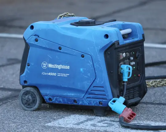
Yes, by connecting a 240V split-phase inverter generator to your hybrid inverter’s AC generator input. The inverter rectifies generator power into the 48V battery bank while simultaneously powering the EV charger through an internal automatic transfer switch, bypassing solar panels entirely during prolonged winter storms.
9. What is the difference between charging a Tesla with NACS vs J1772 off-grid?
A native NACS charger connects directly to the vehicle without mechanical adapter pins. Using third-party J1772-to-NACS adapters under continuous 32A/40A loads introduces contact resistance and localized heating, which often triggers Tesla’s automated 25% thermal current derating. Dedicated chargers like the WOLFBOX PE40T eliminate adapter resistance completely.
10. How many miles of range per hour do you get from off-grid solar EV charging?
A 120V Level 1 off-grid charger adds 3 to 5 miles per hour, while an off-grid 240V Level 2 charger throttled to 16A adds 12 to 15 miles per hour. Dialing current up to 24A adds 18 to 22 miles per hour, allowing an off-grid homeowner to fully replenish a typical 35-mile daily commute in under two hours of peak afternoon sunlight.