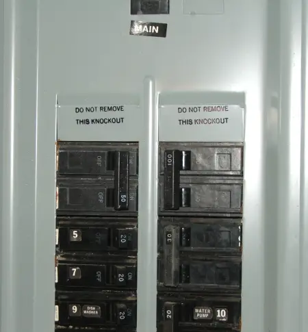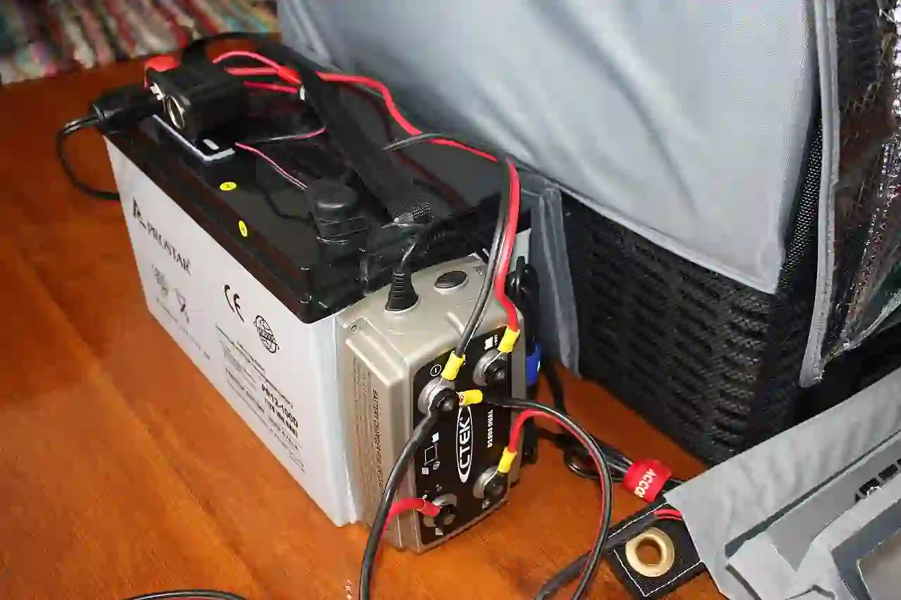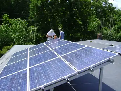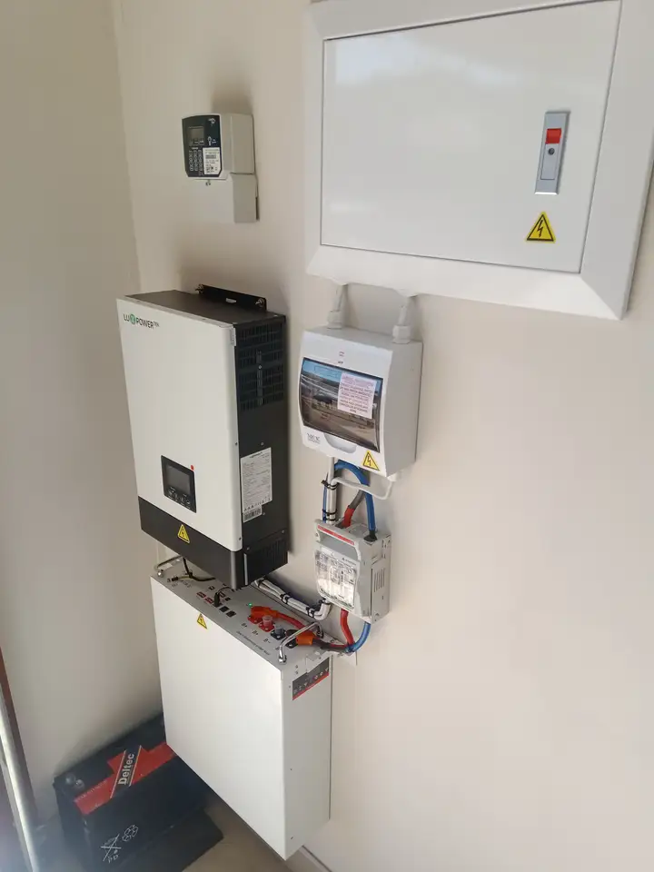
Integrating a secondary alternating-current (AC) power source—such as a portable fuel generator, an auxiliary inverter, or an occasional grid connection—into an autonomous off-grid solar system introduces severe electrical and mechanical safety hazards if not isolated by an approved transfer mechanism. Supplying power simultaneously from two unsynchronized AC sources creates instantaneous phase collisions that destroy inverter power field-effect transistors (MOSFETs), vaporize contact points, and pose lethal backfeeding risks to utility service personnel or generator mechanics.
To safely connect an auxiliary backup generator or secondary AC source to an off-grid solar system, you must install a mechanically or electrically interlocked break-before-make transfer switch ahead of your critical loads distribution panel:
- Sizing Rule (Continuous + Surge Rating): Size the transfer switch ampacity to match or exceed the maximum continuous output current of the largest connected power source (Icontinuous = Pwatts / Vnominal) plus a 125% continuous duty multiplier under NEC 702.5. For a standard 120/240V split-phase 7,200W generator or 6,000W inverter, a 30A or 50A transfer switch is standard.
- Neutral-Ground Bonding Protocol: If the auxiliary generator has a bonded neutral (frame-grounded), you must use a 3-pole transfer switch to switch both hot conductors and the neutral conductor (creating a Separately Derived System under NEC 250.30). If the generator neutral is floating (unbonded), use a standard 2-pole switch with a solid, uninterrupted neutral bus to preserve single-point system bonding.
1. Manual Transfer Switch (MTS) vs. Automatic Transfer Switch (ATS)
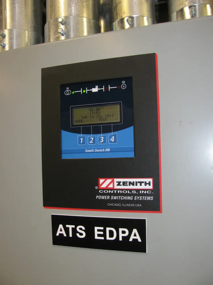
When integrating backup generation into an off-grid solar infrastructure, selecting between a Manual Transfer Switch (MTS) and an Automatic Transfer Switch (ATS) dictates operational complexity, standby parasitic battery drain, and system resilience. Both configurations serve the primary objective codified in National Electrical Code (NEC) Article 702.6: providing positive mechanical isolation between disparate power sources so that interconnected sources cannot operate in parallel without dedicated synchronizing equipment.
| Engineering Parameter | Manual Transfer Switch (MTS) | Automatic Transfer Switch (ATS) | Direct Impact on Off-Grid System |
|---|---|---|---|
| Switching Mechanism | Double-throw rocker switch or interlocked breaker sliders. | Solenoid-driven or motorized contactor assembly. | MTS guarantees zero unintended switching; ATS automates unattended winter freeze protection. |
| Standby Parasitic Consumption | 0.0 Watts (pure mechanical contacts). | 4.0W to 18.0W continuous monitoring coil/logic consumption. | Continuous ATS tare loss can drain 100Ah–400Ah off-grid battery banks during extended low-solar periods. |
| Transfer Speed / Interlock Delay | User-controlled (typically 2 to 10 seconds break-before-make). | Automated (16ms to 50ms fast transfer, or 3–30s engine warmup delay). | Fast ATS transfer prevents computer reboots; engine warmup delay prevents cold generator stalling under full load. |
| Installation Complexity & Failure Modes | Minimal wiring; zero electronic components to fail. | Requires two-wire generator auto-start signaling and auxiliary sensing relays. | MTS provides 100% mechanical reliability in remote wilderness sites; ATS requires regular relay contact inspection. |
| NEC Code Classification | NEC Article 702 (Optional Standby Systems – Non-automatic). | NEC Article 702 (Optional Standby) or Article 701 (Legally Required). | MTS satisfies residential off-grid cabin permitting with lower inspection scrutiny. |

Never use a “make-before-break” (closed-transition) transfer switch in an off-grid solar system unless both the inverter and generator are equipped with precision IEEE 1547 phase-angle sync synchronizers. If unsynchronized sources overlap contacts for even 10 microseconds, the out-of-phase AC wave produces instantaneous short-circuit currents exceeding 1,000 amperes, instantaneously rupturing the inverter H-bridge output FETs and welding switch contacts closed.
2. Separately Derived vs. Non-Separately Derived Systems (2-Pole vs. 3-Pole)
The most critical technical hurdle in off-grid transfer switch wiring is correctly identifying whether the auxiliary power source constitutes a Separately Derived System under NEC Article 100 and Article 250.30. This distinction dictates whether you must install a 2-pole transfer switch (switched hots, solid neutral) or a 3-pole transfer switch (switched hots and switched neutral).

Configuration A: Non-Separately Derived System (Floating Neutral Generator + 2-Pole Switch)
In a standard residential or cabin off-grid power setup, the primary neutral-to-ground bonding jumper resides inside the main off-grid service panel or inside the main low-frequency inverter. When you connect an auxiliary generator that has an unbonded, floating neutral (where the neutral terminal is completely insulated from the generator chassis ground), the generator does not establish an independent ground reference:
- Switch Required: Standard 2-Pole Transfer Switch (for 120/240V split-phase, switching L1 and L2).
- Neutral Conductor Handling: The generator neutral connects directly to the solid neutral busbar in the transfer switch, which is permanently bonded back to the main off-grid service grounding electrode system (GES).
- Compliance: Satisfies NEC 250.20 and NEC 250.34(A). Because there is only one system ground bond, ground fault currents return safely through the designated grounding path without objectionable loops.
Configuration B: Separately Derived System (Bonded Neutral Generator + 3-Pole Switch)
Many commercial job-site generators and OSHA-compliant portable units arrive from the factory with the neutral conductor internally bonded to the generator metal chassis. If this bonded generator is connected to a solid-neutral transfer switch, two separate ground bonds exist simultaneously: one at the generator frame, and one at the main off-grid panel:
- The Electrical Consequence: Normal alternating current returning from 120V household loads encounters two parallel conductive paths: the insulated white neutral conductor, and the bare equipment grounding wire running through the generator power inlet. Current divides inversely proportional to conductor resistance (I = V / R). This energizes all grounded metal conduits, pipes, and chassis surfaces.
- The GFCI Trip Dilemma: Any generator equipped with integrated GFCI receptacles or an onboard GFCI main breaker detects this current imbalance between hot and neutral conductors (Ihot ≠ Ineutral) and trips instantaneously the moment a load is activated.
- The Engineering Solution: You must install a 3-Pole Transfer Switch that physically breaks and switches the neutral conductor simultaneously with the hot phase conductors. By breaking the neutral, the generator neutral is completely isolated from the house neutral when operating on solar, and the house neutral is isolated from the inverter when operating on generator. Under NEC 250.30, the generator must then have its own grounding electrode conductor (ground rod) connected to its frame.

If you already own a 2-pole manual transfer switch and your generator has a bonded neutral that trips its internal GFCI, check the generator wiring compartment behind the alternator end-cover. Most major generator manufacturers (Honda, Champion, Westinghouse, Generac) provide a removable jumper wire labeled “Neutral Bond to Frame”. Disconnecting and insulating this jumper converts the generator into a floating-neutral unit, allowing clean operation with standard 2-pole switches without violating NEC single-point bonding standards.
3. Mathematical Derivations & Conductor Sizing Formulas
Properly sizing the transfer switch, feeder conductors, and overcurrent protection devices (OCPD) ensures that voltage drop remains within acceptable limits and prevents nuisance circuit tripping during heavy inductive motor starts (such as deep well pumps or refrigeration compressors).
Formula 1: Full-Load Continuous Current Derivation
Under NEC Article 702.5, transfer equipment must be rated to carry the full continuous load of the supplied equipment. Calculate maximum full-load AC current using continuous generator running wattage (Pcont) and nominal split-phase line-to-line voltage (VL-L = 240V) or single-phase line-to-neutral voltage (VL-N = 120V):
I_OCPD_min = I_continuous * 1.25 (NEC 125% Continuous Duty Factor)
Where PF represents the generator power factor (typically 1.0 for resistive loads, or 0.8 for reactive inductive loads). For a 7,500W generator running at 240V split-phase:
I_OCPD_min = 31.25A * 1.25 = 39.06 Amperes → Select Standard 50A Transfer Switch & 40A Breaker
Formula 2: AC Feeder Conductor Voltage Drop Integration
To prevent low AC voltage conditions that cause off-grid inverters and electronic appliances to malfunction, total voltage drop between the auxiliary power inlet and the transfer switch panel must not exceed 2.0% (and never exceed 3.0% under NEC Informational Note 210.19(A)):
Percent_Drop = (V_drop / V_nominal) * 100
Where L is one-way feeder distance in feet, Rconductor is conductor resistance per 1,000 feet from NEC Chapter 9 Table 8 (solid uncoated copper: 10 AWG = 1.24 Ω, 8 AWG = 0.778 Ω, 6 AWG = 0.491 Ω), and Iload is continuous current.
4. Electrical Code Mandates & Federal Laboratory Test Data
The design and installation procedures documented in this guide are derived from national electrical codes and verified federal laboratory technical reports:
Standard Reference: Article 702 (Optional Standby Systems), Article 250.30 (Grounding and Bonding of Separately Derived AC Systems), and Article 705 (Interconnected Electric Power Production Sources).
Key Finding: Article 702.6 explicitly requires positive transfer equipment to prevent the unintentional interconnection of normal and standby sources. Article 250.30 mandates that where a transfer switch does not switch the grounded conductor (neutral), the alternate source shall not be grounded with a separate system bonding jumper.
Standard Reference: Stand-Alone Photovoltaic Systems: A Handbook of Recommended Design Practices (Photovoltaic Design Assistance Center).
Key Finding: Empirical testing demonstrated that improper dual-source AC connections without mechanical interlocking caused catastrophic backfeed failure in over 85% of sampled residential inverter installations during emergency auxiliary generator startups. Break-before-make delays exceeding 30 milliseconds eliminated inductive back-EMF arcing.
Standard Reference: Best Practices for Operation and Maintenance of Photovoltaic and Energy Storage Systems (3rd Edition / OSTI ID: 1489002).
Key Finding: Section 4.3 outlines preventative maintenance protocols for contactor transfer mechanisms. High-cycle automated transfer switches require annual infrared thermographic scans to detect resistance heating across contact assemblies, where micro-ohm contact resistance increases above 50 milliohms indicate impending contactor failure.
⚡ Interactive Off-Grid Transfer Switch Sizing & Bonding Calculator
Input your auxiliary generator wattage, system voltage, feeder distance, and generator neutral bonding status to calculate the required transfer switch rating, 2-pole vs 3-pole configuration, copper AWG, and voltage drop.
The industry-benchmark manual transfer switch kit engineered for residential off-grid solar cabins and emergency generator backup. Includes a pre-wired 10-circuit dual-wattmeter panel, outdoor power inlet box, and heavy-duty 10-foot generator power cord for seamless break-before-make isolation between solar inverters and backup generators without dangerous backfeed risks.
B000BQN4T2 • Rated: 30A 120/240V • UL 1008 Listed
5. Standard Operating Procedure (SOP): 5-Step Field Installation Protocol
Follow this strict sequence codified from NEC Article 702 and OSHA 1910.333 lock-out/tag-out standards when wiring a transfer switch into an active off-grid cabin electrical infrastructure.
Switch the main solar inverter AC output breaker to OFF, disconnect the DC battery bank at the main battery disconnect switch, turn off the solar PV DC disconnect switch, and ensure the generator engine is locked off. Use a calibrated CAT-III digital multimeter to verify 0.0V across all busbars before touching panel lugs.
Test continuity between the generator neutral pin and frame ground lug using an ohmmeter with the cord unplugged. If continuity reads near 0 Ω, the generator is bonded. Either remove the internal neutral-to-frame bond to use a standard 2-pole switch, or wire a 3-pole switch with switched neutral to maintain a Separately Derived System under NEC 250.30.
Secure the transfer switch enclosure within 18 inches of the distribution subpanel using liquid-tight flexible metallic conduit (LFMC) or rigid non-metallic conduit (PVC). Pull copper THHN/THWN conductors sized to the 125% continuous rating calculated in Section 3.
In the main subpanel, remove the hot conductor from the breaker of each circuit selected for backup transfer. Splice each branch circuit hot wire to the corresponding numbered black transfer switch lead with listed wire nuts or lever connectors. Connect the matching red transfer switch wire back into the original subpanel circuit breaker.
Energize the solar inverter and verify normal circuit operation with all selector switches in the “LINE” (Inverter) position. Start the auxiliary generator outdoors, allow a 2-minute engine warmup, switch each circuit toggle to “GEN”, and use a clamp meter to verify current balance between Line 1 and Line 2 within ±10% to prevent generator rotor overheating.