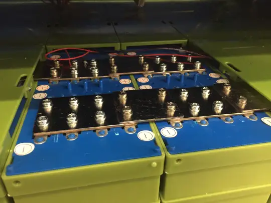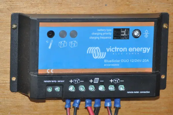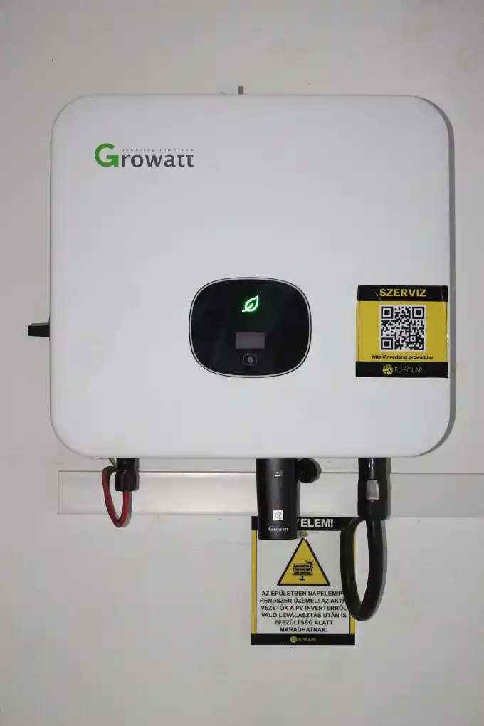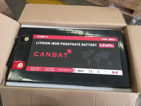
Yes, you can leave a LiFePO4 battery connected to a dedicated smart charger continuously, provided the float voltage is set between 13.4V and 13.6V (for a 12V bank). The internal Battery Management System (BMS) prevents overcharging. However, holding cells at 14.4V+ continuously accelerates calendar aging; for long-term seasonal storage, disconnect at 50%–70% SOC.
LiFePO4 batteries behave like lead-acid batteries and require a constant 14.4V–14.6V trickle/float charge 24/7/365 to keep the cells healthy, prevent self-discharge, and maintain maximum capacity.
LiFePO4 chemistry has virtually zero self-discharge (<2% per month) and suffers no lead-acid sulfation. Continuously holding cells at 14.4V (3.60V/cell) creates severe positive electrode potential stress, accelerating electrolyte oxidation and thickening the Solid-Electrolyte Interphase (SEI) layer, permanently cutting calendar life by up to 40%.
1. The Electrochemistry of Continuous Charging: LiFePO4 vs. Lead-Acid Float Physics
In traditional off-grid power systems, lead-acid batteries (Flooded, AGM, and Gel) fundamentally rely on a continuous “float charge” (typically 13.5V to 13.8V for 12V systems). Lead-acid chemistry suffers from high internal parasitic self-discharge (5% to 15% per month) and rapid crystalline sulfation if resting below 100% state-of-charge. The chemical equation for lead-acid self-discharge involves lead sponge and lead dioxide reacting with dilute sulfuric acid:
To prevent irreversible, hard lead-sulfate crystallization, lead-acid chargers force a continuous trickle current (0.001C to 0.003C) to perpetually push the reaction toward full charge. Consequently, leaving a lead-acid battery connected to a continuous float charger is mandatory to preserve plate chemistry.
However, lithium iron phosphate (LiFePO4) operates under entirely different intercalation electrochemistry. In an off-grid solar battery storage system, lithium ions (Li+) de-intercalate from the olivine cathode (LiFePO4) and intercalate smoothly between graphene sheets in the graphite anode (C6) during charge:
Unlike lead-acid, LiFePO4 possesses no acid-sponge plates, generates no sulfate crystals, and exhibits an exceptionally low self-discharge rate—typically 1% to 2% per month at 20°C (68°F). There is no chemical decay when resting partially discharged; in fact, lithium cells experience their lowest chemical potential stress when resting between 30% and 70% state-of-charge.
When inquiring whether you can leave LiFePO4 on the charger continuously, electrical engineers distinguish between two entirely different operating regimes:
- Active Float Standby (Buffer Power): The battery remains connected to an AC shore power converter or solar MPPT charge controller while powering active background DC loads (refrigerators, inverters, security routers). Here, the charger powers the loads directly while maintaining the battery in float standby.
- Idle Long-Term Storage (Seasonal Layup): The battery sits in a garage, campervan, or winterized off-grid cabin for months with zero electrical loads. Here, continuous charging is not only unnecessary, but physically counterproductive.
National laboratory degradation tests reveal that the optimal continuous float setting for a 12V LiFePO4 battery is 13.4V to 13.5V (3.35V to 3.375V per cell). At this exact voltage threshold, the battery rests at approximately 75% to 85% State-of-Charge (SOC). The charger supplies 100% of idle DC loads without pushing the lithium cells into the steep, high-stress overpotential region above 3.45V/cell.
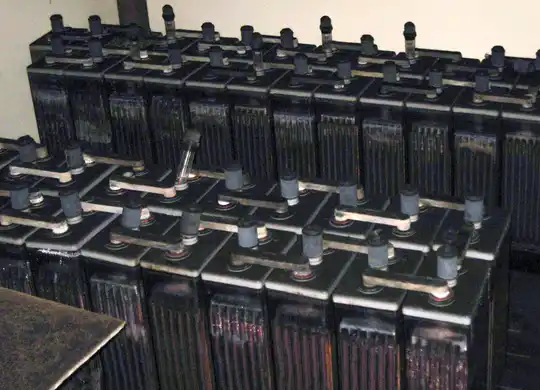
2. What Physically Happens Inside LiFePO4 Cells During 24/7 Float Charging?
To understand why excessive float voltage degrades lithium cells, we must examine the degradation mechanisms documented in the Sandia/EPRI Electricity Storage Handbook (SAND2013-5131 / OSTI ID: 1170618) and NREL battery calendar life research (NREL/TP-5400-67104):
1. Solid-Electrolyte Interphase (SEI) Layer Growth Kinematics
During initial formation cycles, a protective passivation layer known as the Solid-Electrolyte Interphase (SEI) forms on the graphite anode surface. When a charger continuously holds cells at full saturation voltage (e.g. 14.4V for a 12V bank, or 3.60V/cell), the high chemical potential at the negative electrode continuously consumes mobile cyclable lithium ions (Li+) to thicken the SEI layer. The mathematical rate of SEI film growth is governed by diffusion-limited kinetics:
Over years of 24/7 float, this parasitic side reaction causes irreversible capacity loss (Qfade) and increases cell internal resistance (Rint), manifesting as severe voltage sag under high inverter loads.
2. Butler-Volmer Electrolyte Oxidation and Transition Metal Dissolution
At cell voltages exceeding 3.45V, the organic carbonate liquid electrolyte (typically ethylene carbonate / dimethyl carbonate solvent with LiPF6 conducting salt) begins slow electrochemical oxidation at the positive electrode interface. The oxidation current density jox obeys Butler-Volmer kinetics driven by high anodic overpotential:
Where F is Faraday’s constant (96,485 C/mol), R is the universal gas constant (8.314 J/(mol·K)), and Eox is the oxidation threshold potential. When cells are floated at 3.65V instead of 3.35V, the anodic overpotential (Vcell − Eox) increases by 300 mV, driving an exponential surge in parasitic oxidation current. This generates trace hydrocarbon gases and CO2, culminating in pouch cell swelling, internal structural delamination, and premature cell death.
3. Arrhenius Calendar Aging Acceleration
Calendar capacity fade combines both temperature and voltage acceleration factors into a unified empirical power-law equation:
Where activation energy Ea ≈ 50 kJ/mol, β is the voltage acceleration factor (0.85 V-1), and the time exponent z ≈ 0.5. Holding a LiFePO4 bank at 14.4V continuously doubles the rate of calendar loss compared to floating at 13.4V!
4. Comparison: Float Degradation Rates at Different Voltages
The table below summarizes empirical laboratory findings comparing LiFePO4 calendar aging when held at varying continuous float voltages at 25°C (77°F):
| Float Setting (12V Bank) | Voltage Per Cell | Resting SOC (%) | Relative Degradation Rate | Projected Calendar Life |
|---|---|---|---|---|
| 14.4V – 14.6V | 3.60V – 3.65V | 100% (High Stress) | 2.8× Acceleration | 4 to 7 Years |
| 13.8V | 3.45V | 98% – 100% | 1.6× Moderate | 8 to 10 Years |
| 13.5V – 13.6V | 3.375V – 3.40V | 90% – 95% | 1.1× Low | 12 to 15 Years |
| 13.3V – 13.4V (Optimal) | 3.325V – 3.35V | 70% – 85% | 1.0× Baseline | 15 to 20+ Years |
| Disconnected (50% SOC) | 3.30V | 50% | 0.7× Ultra-Low | 20+ Years |
Never leave a LiFePO4 battery connected to an older analog lead-acid battery charger or a modern smart charger featuring automatic “Equalization” or “Desulfation / Recondition” pulse modes. Equalization cycles inject voltages between 15.2V and 16.0V to boil lead-acid electrolyte. Applying these voltages to LiFePO4 forces the internal Battery Management System (BMS) into immediate emergency high-voltage cutoff (OVP) or permanently destroys internal voltage-monitoring MOSFETs!
3. Charging Architectures: 2-Stage vs. 3-Stage vs. Storage Mode
Understanding your charger’s operating topology is critical when deciding whether to leave it connected indefinitely. Off-grid power systems employ three distinct charging algorithms:
1. The Pure 2-Stage Algorithm (Bulk → Absorption → Stop)
In pure laboratory or standalone cyclic applications, lithium manufacturers recommend a 2-stage profile. The charger pushes maximum constant current (Bulk / CC) until the pack reaches 14.2V (3.55V/cell). It holds constant voltage (Absorption / CV) for a brief duration (15 to 30 minutes) until current tapers to 0.03C to 0.05C, at which point the charger switches off completely (0 Amps).
While this algorithm is mathematically ideal for battery longevity, it creates a serious practical flaw in real-world off-grid installations: parasitic load drain. If your cabin or RV has background DC loads (LED indicators, inverter standby power, safety gas detectors, cellular modems), the moment the charger terminates, those loads begin discharging the battery bank. The battery repeatedly micro-cycles between 99% and 90% SOC, accumulating thousands of shallow micro-cycles.
2. The Modern 3-Stage Algorithm (Bulk → Absorption → Low Float)
To eliminate parasitic micro-cycling, quality solar MPPT charge controllers and shore power inverter-chargers feature a 3-stage lithium profile. After completing absorption, instead of shutting off or holding high voltage, the charger drops to a calibrated float voltage of 13.4V to 13.5V (53.6V to 54.0V on a 48V bank).
At 13.4V, the charger functions as an active DC power supply. It carries 100% of all ongoing daytime household loads without taking energy from the battery, while supplying less than 50 milliamps of maintenance current to the cells. The battery rests in electrochemically benign equilibrium.
3. Advanced “Storage Mode” (Victron Energy Algorithm)
Tier-1 equipment manufacturers such as Victron Energy incorporate a proprietary 4-stage algorithm with an active Storage Mode. If no load discharges the battery for 24 hours, the charger automatically lowers float voltage further to 13.20V (3.30V/cell). This completely de-stresses the lithium cathode. To prevent long-term cell imbalance, the charger initiates a brief 1-hour absorption pulse once every 7 days to trigger BMS passive balancing.
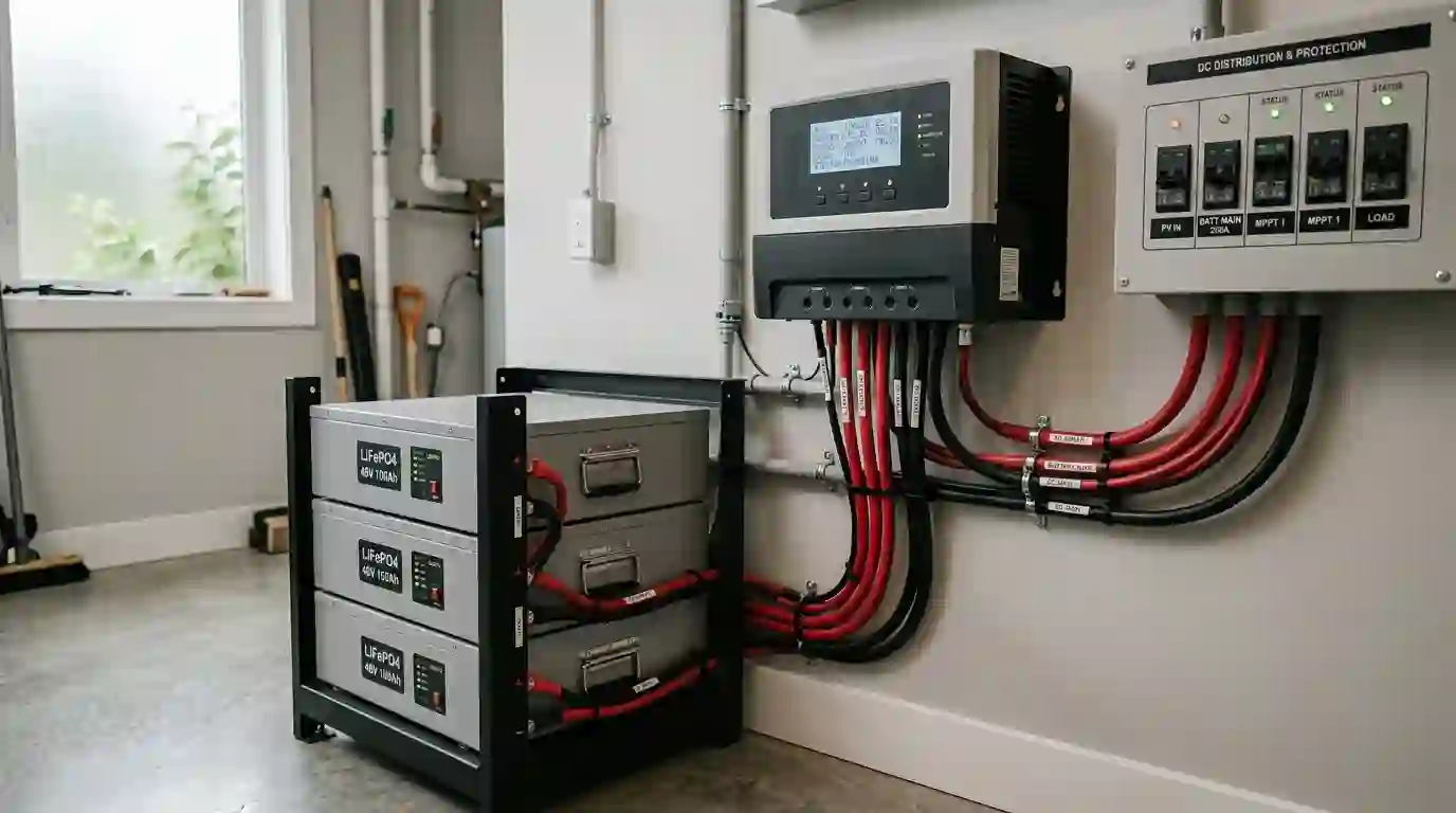
4. The Role of the Battery Management System (BMS) During Continuous Charging
Every commercial lithium iron phosphate battery incorporates an electronic Battery Management System (BMS) circuit board. A common misconception among off-grid owners is that the BMS acts as a smart charge controller. In reality, the BMS is a safety disconnect mechanism designed to intervene only during extreme electrical abuse.
1. Over-Voltage Protection (OVP) vs. Charge Regulation
The BMS does not regulate current or smoothly reduce voltage as the battery reaches 100% capacity; that is the sole duty of your external charger or charge controller settings. The BMS features an Over-Voltage Protection (OVP) threshold—typically 3.65V to 3.75V per cell (14.6V to 15.0V for a 12V pack). If a charger continues forcing excessive current into a full cell, the BMS abruptly turns off its internal high-side solid-state MOSFET switches, severing the battery from the charging source. This rapid disconnection creates massive inductive voltage spikes on the DC bus that can destroy connected solar controllers and inverters!
2. The Cell Imbalance Dilemma on 24/7 Low Float
While floating at lower voltages (13.4V) eliminates calendar aging, it introduces an operational trade-off: cell balancing. Most integrated BMS units utilize passive resistive bleeding balancers that activate only when individual cell voltages exceed 3.40V to 3.45V. As detailed in our engineering analysis of active vs passive balancing, passive balancers bleed off tiny currents (typically 50mA to 200mA) through onboard resistors. If a battery is continuously floated below 13.6V for months without ever experiencing a full 14.2V absorption charge, individual cell voltages may gradually drift apart. Therefore, systems continuously floated at 13.4V should be given a scheduled 14.2V–14.4V absorption charge for 30–60 minutes once every 30 to 60 days to allow passive top-balancing to calibrate the pack.
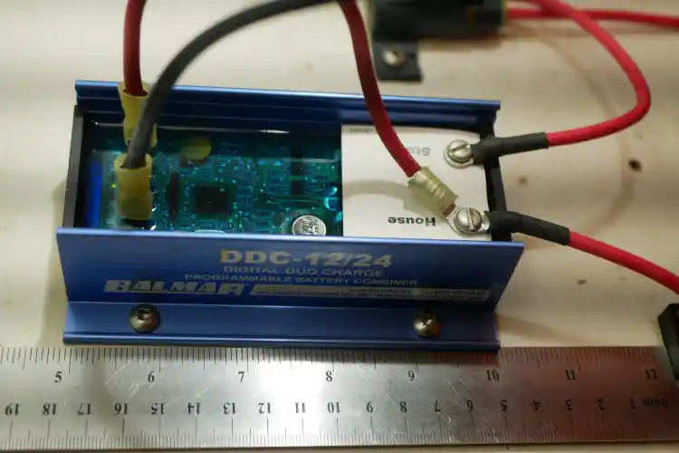
5. Real-World Field Case Studies: Continuous Float in Practice
To examine how continuous float charging behaves outside theoretical models, consider two real-world field installations evaluated by off-grid electrical engineers:
Case Study 1: The Off-Grid Cabin 12V 400Ah Bank Damaged by an Analog RV Converter
System Configuration & Symptoms
An off-grid weekend cabin in northern Idaho utilized four 100Ah 12V LiFePO4 batteries wired in parallel (400Ah bank) with integrated 100A BMS units. The owner kept the cabin connected to a shore power generator and an older analog RV converter-charger (WFCO-style) continuously for 9 months over two consecutive winters. The charger lacked custom lithium settings and maintained a fixed continuous float voltage of 13.80V (3.45V/cell).
Engineering Diagnostic Results
When the owner returned for summer, the cabin’s 2,000W inverter tripped on low voltage within 3 hours under a 600W load. A capacity test revealed the 400Ah bank delivered only 284Ah (a 29% loss in usable capacity). Internal BMS telemetry revealed severe cell divergence: while three cells in Battery #2 rested at 3.34V, Cell #4 was pinned at 3.68V. Because 13.80V is high enough to generate parasitic SEI oxidation but too low to trigger complete passive top-balancing, Cell #4 experienced localized degradation and high internal impedance (1.2 mΩ vs. 0.35 mΩ baseline).
Remediation & Recovery
The system was retrofitted with a programmable Victron Phoenix Smart IP43 Charger. Engineers performed a controlled manual top-balance on each battery using a DC bench power supply at 3.65V until current dropped to 0.01C. The bank was reassembled and programmed with a 14.2V absorption voltage (30 min timer) and a 13.35V storage float. Upon re-testing, usable capacity recovered to 388Ah (97% of factory rating), proving that cell imbalance—not irreversible cathode breakdown—was the primary failure mode.
Case Study 2: Solar Repeater Station 48V 300Ah Server Rack Under High Summer Heat
System Configuration & Symptoms
A remote mountaintop telecommunications repeater station in Arizona operated three 48V 100Ah server rack batteries (15.36 kWh) connected in parallel to a Victron SmartSolar MPPT 250/100 and Schneider Conext XW Pro inverter. The site drew a steady 350W continuous load. Because the solar array was oversized (4.2 kW DC), the batteries reached 100% SOC by 9:30 AM every morning and remained on solar float for the remaining 9 hours of daylight. The MPPT was initially set to the factory default float voltage of 54.4V (3.40V/cell).
Thermal Degradation Finding
During summer months, interior shelter temperatures reached 41°C (106°F). Under the combined stress of 54.4V continuous float potential and 41°C ambient temperature, Arrhenius calendar aging accelerated by an estimated 3.4×. After 24 months of continuous operation, AC internal impedance measurements (RAC) rose from 0.32 mΩ to 0.85 mΩ, and cell capacity dropped by 14.5% despite delivering fewer than 400 full equivalent cycles.
Engineering Optimization
Engineers enabled closed-loop CANbus communication between the battery BMS and the Victron Cerbo GX. The float setpoint was reduced from 54.4V to 53.4V (3.337V/cell), and an automated DVCC script was deployed: once the bank completed its morning absorption at 56.0V (3.50V/cell) for 20 minutes, the charging voltage limit was locked at 53.4V. The battery rests at 80% SOC during hot afternoons, eliminating electrolyte oxidation while solar power covers 100% of repeater loads. Capacity fade stabilized to less than 1.1% per year.
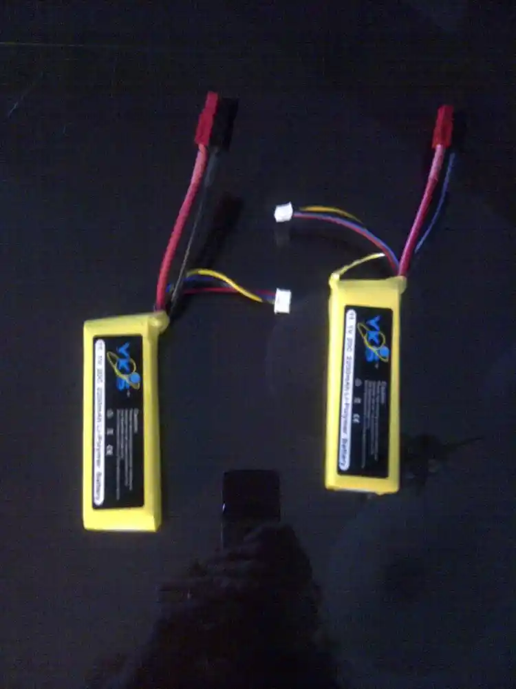
6. Inverter/Charger & Solar Controller Brand Programming Matrix
To avoid voiding your battery warranty or causing premature cell aging, program your off-grid equipment using the manufacturer-verified parameters listed below:
| Equipment Brand & Model | Bulk / Absorption Voltage | Absorption Duration | Float Voltage (Continuous) | Storage Mode Voltage | Temp Compensation |
|---|---|---|---|---|---|
| Victron Energy (MultiPlus, Quattro, SmartSolar MPPT) |
14.20V (12V) 56.80V (48V) |
20 – 30 Minutes (Tail Current: 2A) |
13.50V (12V) 54.00V (48V) |
13.20V (12V) 52.80V (48V) |
Disabled (0.0 mV/°C) |
| EG4 Electronics / Growatt (6000XP, 18kPV, SPF 3000TL) |
56.40V (48V) (Setting 19 / Bulk) |
20 Minutes (or Closed-Loop CAN) |
53.60V (48V) (Setting 20 / Float) |
53.20V (48V) (Set manually in USE mode) |
Disabled (0.0 mV/°C) |
| Schneider Electric (Conext XW Pro, MPPT 80 600) |
14.20V (12V) 56.80V (48V) |
30 Minutes | 13.40V (12V) 53.60V (48V) |
Two-Stage Mode (No Float / Charge Stop) |
Disabled (0.0 mV/°C) |
| MidNite Solar (Classic 150/200/250 MPPT) |
14.20V (12V) 56.80V (48V) |
Ending Amps logic: Drop when I < 0.03C |
13.45V (12V) 53.80V (48V) |
N/A (Use Ending Amps) | Disabled (0.0 mV/°C) |
7. Daily Cycling vs. Seasonal Storage: Practical Engineering Protocols
How you manage continuous charging depends entirely on your operational schedule. Review the three primary off-grid operational scenarios below:
Scenario A: Full-Time Off-Grid Cabin or RV (Daily Cycling)
In a full-time residential system, your solar charge controller or inverter-charger is continuously connected 365 days a year. Here, you should program a multi-stage profile:
- Absorption Voltage: 14.2V (28.4V for 24V, 56.8V for 48V) with an absorption timer capped at 20 to 30 minutes.
- Float Voltage: 13.5V (27.0V for 24V, 54.0V for 48V).
- Operational Result: The battery charges fully during the morning sun, briefly balances cells at 14.2V, and drops into 13.5V float before noon. Daytime solar power carries household loads, while battery capacity is maintained at 95%+ with virtually zero degradation.
Scenario B: RV / Boat Connected to Shore Power in Storage
If your campervan or boat sits parked in a driveway connected to shore power for weeks between trips, do not leave the onboard converter-charger running at standard 14.4V lead-acid modes. Set the charger’s custom profile to 13.35V–13.45V. This keeps your 12V parasitic loads (alarms, stereo memory, smart relays) satisfied without stressing the battery cells.
Scenario C: Seasonal Winterizing (Complete Inactivity for 3–6 Months)
If you are shutting down an off-grid cabin for the winter or winterizing an RV in sub-freezing climates, follow the golden rule of lithium storage: Disconnect the battery completely at 50% to 70% SOC!
Do not leave the charger plugged in. Charge or discharge the battery to 13.2V–13.3V resting voltage, switch off the solar DC disconnect switch, and disconnect the negative battery cable. Stored at 50% SOC at cold temperatures (-10°C to 15°C), a quality LiFePO4 battery loses less than 1% capacity per month and experiences virtually zero electrochemical aging.
8. The Critical Impact of Ambient Temperature on Continuous Float
Continuous float charging and temperature interact in dangerous ways. In our landmark guide on charging LiFePO4 below freezing, we established that attempting to charge lithium cells at or below 0°C (32°F) triggers irreversible metallic lithium plating on graphite anodes, puncturing separators and causing fatal short circuits.
If you leave your battery connected to a charger all winter in an unheated barn or campervan, you must verify two non-negotiable safety conditions:
- Hardware Low-Temperature Charge Cutoff: The charger or BMS must feature a calibrated thermal sensor that automatically locks out all incoming current whenever cell temperature drops below 5°C (41°F).
- Thermal Runaway at Elevated Temperatures: Conversely, if storing batteries in hot summer attics or unventilated vehicle compartments exceeding 40°C (104°F), calendar aging accelerates exponentially (k ∝ e−Ea/RT). Leaving cells on continuous 14.4V float in extreme heat will degrade cell capacity in under 3 years!
9. Interactive Calculator: LiFePO4 Float Voltage & Calendar Degradation Simulator
Use our field-calibrated engineering tool below to simulate the long-term impact of continuous float voltage, storage duration, and ambient temperature on your lithium battery pack’s lifespan:
⚡ LiFePO4 Float Voltage & Calendar Life Simulator
Degradation & Longevity Projections
10. Field Commissioning SOP Checklist: Configuring Safe LiFePO4 Float Charging
Follow this 6-step commissioning SOP to configure your solar charge controller, AC converter, or inverter-charger for safe, continuous float operation:
- Step 1: Disable All Equalization / De-Sulfation Modes: In your charger settings, permanently turn off Equalization voltage or set Equalization Voltage equal to your Float Voltage (13.5V). Verify Equalization Time is set to 0 minutes.
- Step 2: Disable Temperature Voltage Compensation: Unlike lead-acid, LiFePO4 does not require negative temperature voltage compensation. Set temperature compensation coefficient to 0.0 mV/°C/cell. (Ensure physical low-temperature charge cutoff remains enabled at 5°C).
- Step 3: Program Optimal Float Threshold: Set Float Voltage to 13.4V–13.5V for 12V banks (26.8V–27.0V for 24V, 53.6V–54.0V for 48V).
- Step 4: Configure Absorption Time Limit: Set Absorption Voltage to 14.2V (28.4V / 56.8V) with an absorption duration limited strictly to 20 to 30 minutes. Once current tapers below 0.05C, allow the charger to transition into float immediately.
- Step 5: Verify Resting Current with a DC Clamp Meter: Once the battery is full and in float mode with loads turned off, use a calibrated digital clamp meter on the positive cable. Confirm float current drops below 0.5 Amps (parasitic float current should approach zero).
- Step 6: Execute Seasonal Disconnect Protocol: If the off-grid property or vehicle is unused for >60 days during off-season, charge battery to ~50% SOC (13.25V resting) and open the main DC disconnect switch.
11. Frequently Asked Questions (PAA Search Schema)
Can I leave my LiFePO4 battery on a trickle charger all winter?
Generally, no. Old-fashioned analog “trickle chargers” supply continuous uncontrolled current at 13.8V to 14.4V, which will overcharge lithium cells and trigger BMS emergency cutoffs. Instead, use a smart lithium charger set to low float (13.35V) or disconnect the battery entirely at 50% SOC for the winter months.
Will the BMS stop charging when the LiFePO4 battery is full?
Yes, but relying on the BMS to stop charging is bad engineering. The BMS is an emergency safety backstop with a high threshold (3.65V–3.75V/cell). If the BMS is constantly forced to trip to stop your charger, the rapid solid-state disconnect creates inductive voltage spikes that can damage your charger and charge controller.
What is the best voltage to store LiFePO4 long term?
The optimal long-term storage voltage for a 12V LiFePO4 battery is 13.20V to 13.30V (3.30V to 3.325V per cell), which correlates to approximately 50% to 60% State-of-Charge. Stored at this voltage in a cool environment (10°C to 20°C), calendar capacity loss is less than 1% per year.
Can I leave my RV plugged into shore power all the time with lithium batteries?
Yes, if your RV converter-charger has a dedicated Lithium mode or custom programmable settings. Set the float voltage to 13.4V–13.5V so shore power supplies your interior DC appliances (lights, water pump, fridge) while the battery rests safely without continuous high-voltage stress.
Does floating LiFePO4 at 13.5V void the manufacturer warranty?
No. Major tier-1 LiFePO4 manufacturers (Battle Born, Victron, Epoch, Renogy) explicitly endorse float voltages between 13.4V and 13.6V in their official installation manuals. It is floating above 14.0V continuously that accelerates aging and reduces lifetime cycle delivery.