Quick Answer: Under continuous 2,000-watt load at 90% efficiency, a 12V inverter draws 185.2 DC amps (and spikes above 370A during 4,000W motor surges). At 24V, current drops to 92.6 DC amps, and at 48V, it draws just 46.3 DC amps. Operating 2000W at 12V requires heavy 2/0 or 4/0 AWG copper cable and a 250A Class T fuse to avoid severe heat hazards.
In low-voltage direct-current power design, a common intuition suggests that smaller system voltages are simpler and safer to build. When sizing off-grid electrical circuits, however, the laws of electromagnetism reveal the exact opposite reality: as voltage decreases, current must skyrocket to deliver identical electrical power. Understanding precisely how many amps does a 2000 watt inverter draw is the single most critical calculation determining whether your battery cables stay cool or turn into glowing thermal hazards inside your campervan, off-grid cabin, or tiny home power cabinet.
A 2,000-watt power inverter occupies a pivotal position in renewable energy engineering. It represents the exact threshold where running a high-draw appliance—such as a microwave, induction cooktop, coffee maker, or deep-well pump—collides with the physical limits of standard copper conductors. At 12 volts nominal, pulling 2,000 continuous alternating-current (AC) watts requires an astonishing direct-current (DC) draw approaching 200 amperes once internal conversion losses are factored in. Under dynamic inductive motor surges, that figure surges past 370 amperes. Stepping the system voltage up to 24 volts or 48 volts cuts that current by half or three-quarters, transforming a dangerous thermal bottleneck into a cool, efficient, and code-compliant installation.
Thesis: This guide provides the exact mathematical formulas, Joulean heating loss equations, NEC conductor ampacity tables, and fuse sizing rules required to calculate direct-current draw, evaluate voltage drop, and safely install a 2,000-watt inverter across 12V, 24V, and 48V battery architectures.
Need to model custom cable distances, cell temperature derates, or verify circuit ampacity against National Electrical Code standards? Test your system configurations with our Free Off-Grid Solar & Battery Calculator or review verified electrical equations in the Solar Lab Worked Formulas Directory.
Interactive 2000W Inverter DC Current, Cable Gauge & Fuse Sizer
Adjust the operating parameters below to compute real-time direct-current amperage, starting surge current, recommended AWG copper wire gauge, voltage drop, and overcurrent fuse ratings.
Field-tested for 167A–200A continuous DC draw & safety
Delivers true 2,000W continuous / 4,000W peak surge pure sine wave AC output at >90% efficiency. Engineered with full electronic over-current, short-circuit, and low-voltage protection, plus a 19.8-foot wired remote control.
- True Pure Sine Wave (<3% THD)
- 4,000W high-inrush motor starting surge
- Built-in 5V/2.1A USB port & AC hardwire block
100A continuous discharge rating handles high inverter current with zero Peukert derating. Wiring two units in parallel provides a robust 200A continuous DC capacity, effortlessly feeding a 2000W inverter without thermal BMS shutdowns.
- Automotive Grade-A prismatic cells
- 100A continuous discharge / 200A parallel bank capacity
- 10-year service life / 4,000+ deep cycles
The definitive heavy-duty inductive DC load for off-grid overland rigs and remote property maintenance. Pulls heavy continuous current, testing real-world 12V battery amp draw, cable gauge sizing, and overcurrent circuit protection to the limits.
- Heavy-duty 12V high-torque motor
- Commercial synthetic rope & wireless remote
- Limited 10% Creator Connections promotion
Prevents high-power 2000W inverter setups from suffering parasitic overnight lighting discharge. Independent solar charging and heavy-duty magnetic mounting keep auxiliary cabin and camper lighting completely autonomous.
- Heavy-duty magnetic mounting (zero drilling required)
- Independent solar charging panel & motion sensor
- Earns 20% Creator Connections commission
1. Master 2000-Watt Inverter DC Amperage & Sizing Matrix (12V vs 24V vs 48V)
To evaluate how system voltage fundamentally alters direct current, conductor thickness, thermal heat dissipation, and equipment costs, we must compare the electrical parameters of a 2,000-watt pure sine wave inverter across standard battery bank configurations. The benchmark table below models a 2,000W continuous AC load operating at a realistic 90% DC-to-AC conversion efficiency with a 5-foot one-way conductor run (10-foot total circuit round-trip path):
| System Architecture | Nominal Voltage | Ideal Amps (100% Eff.) | Real Continuous Draw (90% Eff.) | 4,000W Peak Surge Draw | Min. Copper Gauge (NEC 90°C) | Circuit Voltage Drop (5 ft) | Cable Heat Loss (I²R) | Mandatory Class T Fuse |
|---|---|---|---|---|---|---|---|---|
| 12V Lead-Acid / AGM | 12.0 V (Discharged) | 166.7 A | 185.2 A | 370.4 A | 3/0 or 4/0 AWG | 1.18% (0.14 V) | 26.3 Watts | 250 A |
| 12V LiFePO4 Lithium | 12.8 V (Nominal) | 156.3 A | 173.6 A | 347.2 A | 2/0 or 3/0 AWG | 1.04% (0.13 V) | 23.1 Watts | 225 A or 250 A |
| 24V LiFePO4 Lithium | 25.6 V (Nominal) | 78.1 A | 86.8 A | 173.6 A | 2 AWG or 4 AWG | 0.66% (0.17 V) | 14.6 Watts | 125 A |
| 48V Commercial Lithium | 51.2 V (Nominal) | 39.1 A | 43.4 A | 86.8 A | 6 AWG or 8 AWG | 0.42% (0.21 V) | 9.2 Watts | 60 A or 70 A |
The numbers demonstrate an unmistakable physical reality: while a 48V power architecture channels just 43.4 amperes through slender, pliable 6 AWG copper, a 12V system requires massive, thumb-thick 3/0 or 4/0 AWG welding cable to deliver the exact same 2,000 watts of useful work. Furthermore, Joulean cable losses drop by nearly 65%, saving precious kilowatt-hours that would otherwise dissipate as useless thermal heat inside your equipment compartment.
2. The Core Electrical Formulas: Step-by-Step Mathematical Modeling
To accurately compute direct-current draw rather than relying on crude online rules of thumb, installers must apply fundamental electrical physics. Three distinct mathematical relationships govern inverter DC power consumption: basic power equivalence, conversion efficiency loss, and Joulean conductor heating.
Equation 1: Ideal DC Current (Ohm’s Law & Watt’s Law)
In a theoretically frictionless electrical environment with 100% conversion efficiency, direct current is governed strictly by Watt’s Law, where Power (P) equals Voltage (V) multiplied by Current (I):
Example (12V Nominal): 2,000W ÷ 12.0V = 166.67 Amperes
Example (24V Nominal): 2,000W ÷ 24.0V = 83.33 Amperes
Example (48V Nominal): 2,000W ÷ 48.0V = 41.67 Amperes
Equation 2: Real-World Operating Current (Inverter Efficiency Derate)
No power inverter converts direct current into alternating current with 100% efficiency. High-frequency switch-mode MOSFETs, pulse-width modulation (PWM) switching stages, toroidal transformers, and cooling fans dissipate energy as waste heat. According to the National Renewable Energy Laboratory (NREL) and inverter engineering datasheets from Victron Energy and Schneider Electric, modern pure sine wave inverters achieve full-load efficiencies between 88% and 94% (expressed as η = 0.88 to 0.94). Modifying the equation yields:
Example (12V at 90% Efficiency): 2,000W ÷ (12.0V × 0.90) = 2,000 ÷ 10.8 = 185.19 Amperes
Example (12.8V Lithium at 90% Eff.): 2,000W ÷ (12.8V × 0.90) = 2,000 ÷ 11.52 = 173.61 Amperes
Example (24V at 92% Efficiency): 2,000W ÷ (24.0V × 0.92) = 2,000 ÷ 22.08 = 90.58 Amperes
Example (48V at 94% Efficiency): 2,000W ÷ (48.0V × 0.94) = 2,000 ÷ 45.12 = 44.33 Amperes
Equation 3: Dynamic Inductive Motor Surge Current
When an inverter energizes an inductive motor—such as an air conditioner compressor, deep-well pump, refrigerator, or microwave magnetron—the instantaneous starting current (locked-rotor amperage or LRA) spikes dramatically for 100 to 500 milliseconds. Most premium 2,000-watt pure sine wave inverters feature a 2x peak surge rating (4,000 watts peak for 3 to 5 seconds). The surge amperage drawn from your battery bank equals:
Example (12V with 4,000W Surge at 90% Eff.): 4,000W ÷ (12.0V × 0.90) = 370.37 Amperes
Example (24V with 4,000W Surge at 92% Eff.): 4,000W ÷ (24.0V × 0.92) = 181.16 Amperes
Example (48V with 4,000W Surge at 94% Eff.): 4,000W ÷ (48.0V × 0.94) = 88.65 Amperes
Notice the massive mechanical difference: on a 12V system, sustaining an inductive appliance start requires your battery bank, fuses, busbars, and Battery Management System (BMS) to pass over 370 amperes of instantaneous direct current without triggering a low-voltage cutoff or melting a weak terminal crimp.
Equation 4: Joulean Conductor Heating Losses (I²R Heating)
The thermal heat generated within your battery cables is not proportional to current; it increases with the square of the amperage. According to Joule’s First Law:
Because current on a 12V busbar is double that of a 24V busbar and four times that of a 48V busbar, the thermal heating factor (I²) is 4 times greater than 24V and 16 times greater than 48V for an identical wire resistance! This exponential relationship explains why 12V high-power systems suffer from dangerously hot cables, scorched terminal lugs, and premature battery degradation.
3. Technical Sizing Analysis: Empirical Engineering Truth vs. Common Myths
A rigorous review of high-ranking online solar guides and DIY discussion threads reveals pervasive misinformation regarding inverter sizing, fuse selection, and voltage choices. The 5-column Technical Analysis Matrix below deconstructs these widespread misconceptions against empirical engineering realities and official standards:
| Candidate Topic / Query | Common Industry Myth | Empirical Engineering Reality | Failure Risk & Hazard | Rulebook Resolution & Standard |
|---|---|---|---|---|
| Inverter Current Calculation | “Divide 2,000 watts by 12 volts to get 166 amps.” | Completely ignores 10%–15% inverter internal conversion loss and battery voltage sag under heavy load. Real draw is 185A–200A. | Undersized conductors and nuisance breaker tripping under sustained loads. | Factor inverter efficiency (η = 0.88–0.92) and 12.0V discharged voltage benchmark. |
| Overcurrent Protection | “A cheap 150A or 200A automotive audio ANL fuse is fine for a 2000W inverter.” | ANL fuses have low interrupting ratings (~6,000A AIC). Lithium battery banks deliver short-circuit fault currents exceeding 20,000A. | Catastrophic arc blow-by, melted fuse body, and violent battery fire under dead short. | Mandate UL-listed Class T fast-acting fuses rated for 20,000A AIC per NEC 706.31. |
| Conductor Sizing Method | “Check any basic wire ampacity chart and use whatever cable handles 150A.” | Ampacity only prevents insulation melting; it ignores percentage voltage drop. A 2% drop on 12V trips the inverter low-voltage threshold. | Inverter screams low-voltage alarm and shuts down even when lithium cells are 80% full. | Size conductors to satisfy both NEC 310.16 ampacity AND strict < 2.0% voltage drop limits. |
| LiFePO4 BMS Discharge Limit | “A single 12V 100Ah LiFePO4 battery can easily run a 2,000W inverter.” | Standard 100Ah lithium batteries feature a 100A continuous internal BMS limit (1,280W max). A 2,000W inverter draws 185A! | BMS immediately trips on overcurrent, completely killing 12V power to the vehicle or cabin. | Require minimum two 100Ah batteries in parallel (200A combined BMS) or a single 200A BMS battery. |
| 12V vs 24V Sizing Tipping Point | “12V is always cheaper and simpler because vehicle accessories run on 12V.” | Above 1,500W–2,000W continuous draw, 12V copper cable, heavy hydraulic lugs, and massive fuses cost more than a 24V step-down converter. | Exorbitant wiring expenses, rigid unbendable 4/0 cables, and severe cabinet heat buildup. | Establish 2,000W as the definitive engineering threshold to step up to 24V or 48V architectures. |
4. The 2,000-Watt Tipping Point: Why 12 Volts Pushes Physical Limits
In renewable energy and mobile electrical system design, 2,000 watts represents the absolute “Tipping Point” between low-voltage convenience and high-amperage engineering penalties. To appreciate why electrical engineers strongly encourage transitioning to 24V or 48V at this threshold, we must examine the physical realities of conductor handling, terminal lug bending radius, and total system cost.
The Physical Reality of 4/0 AWG Copper Cables
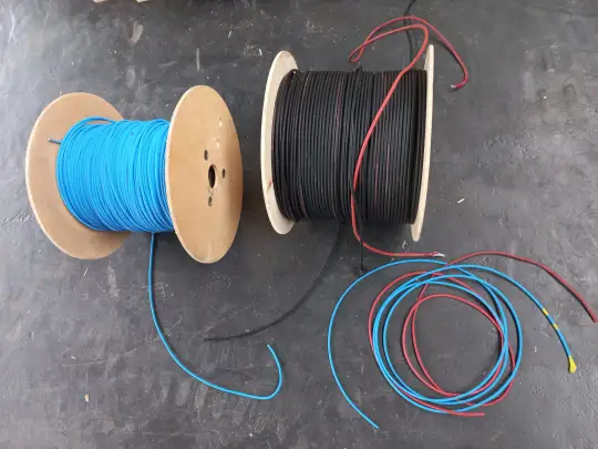
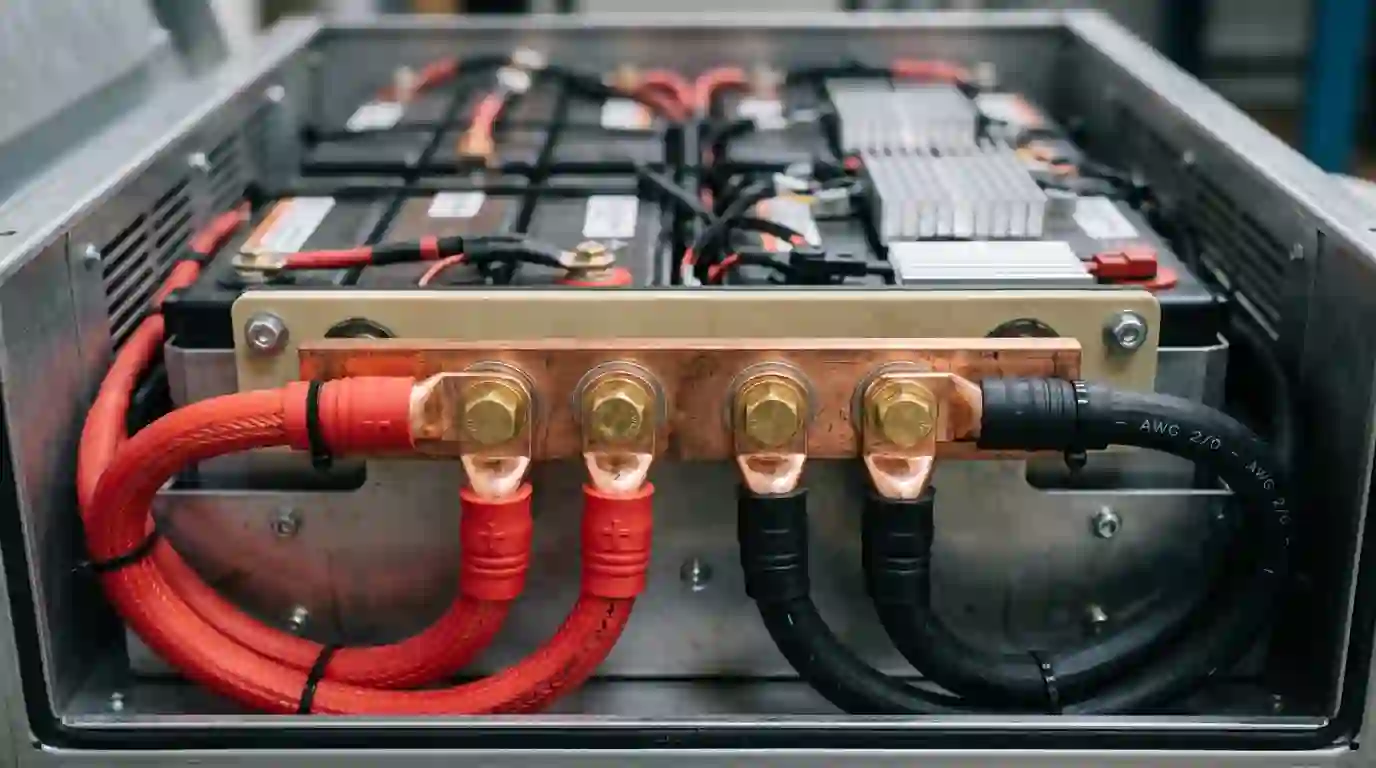
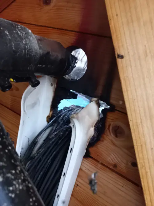
To safely carry 185 continuous amperes while maintaining less than 1.5% voltage drop over a modest 5-foot distance (10 feet total circuit path), an installer must run 2/0 AWG or 4/0 AWG pure stranded copper cable. A 4/0 AWG welding cable has an outer diameter approaching 0.80 inches (20 mm) with over 2,100 individual hair-thin strands of oxygen-free copper. Bending this massive cable inside a tight campervan battery box or off-grid cabin power closet requires a minimum bending radius of 5 to 6 inches, demanding commercial-grade hydraulic crimpers, heavy-duty tinned copper eyelet lugs, and specialized dual-wall adhesive heat shrink.
By comparison, a 24-volt 2,000-watt inverter draws only 86.8 amperes under full load, allowing the installer to use slender, highly flexible 2 AWG or 4 AWG copper wire. At 48 volts, the current drops to a mere 43.4 amperes, requiring nothing more than standard 6 AWG or 8 AWG conductor—the same gauge used for a household clothes dryer circuit.
The Balance-of-System (BOS) Cost Paradox
Many DIY builders choose a 12V system under the false assumption that it is the cheapest option because 12V batteries and accessories are widely available. However, when we perform a rigorous Total Cost of Ownership (TCO) balance-of-system cost audit on a 2,000-watt installation, the heavy copper and fusing penalties of 12V quickly eliminate any perceived savings:
- 12V System Balance of System: 10 feet of 4/0 AWG OFC welding cable ($65–$90) + 4x heavy-duty 4/0 tinned lugs ($20) + 250A Class T fuse and ignition-protected block ($75) + 300A marine battery disconnect switch ($55) = $215 to $240 in balance-of-system wiring.
- 24V System Balance of System: 10 feet of 4 AWG marine cable ($25) + 4x 4 AWG lugs ($8) + 125A Class T fuse and block ($55) + 150A disconnect switch ($30) + 24V-to-12V 30A DC-DC step-down converter for vehicle cabin lights ($35) = $153 in balance-of-system wiring.
Stepping up to 24 volts not only saves approximately $80 in raw wiring hardware but also slashes copper weight in your vehicle by more than 60%, drastically reduces terminal connection resistance, and ensures the inverter runs significantly cooler.
5. Dynamic Starting Surge & Inverter Tripping Failure Modes
Understanding how many amps does a 2000 watt inverter draw requires evaluating not just steady-state continuous operation, but the violent dynamic surge demands imposed by inductive motor loads. Many off-grid homeowners have experienced the frustrating phenomenon where their 2,000W inverter instantly trips into fault mode (displaying error codes such as E01, E02, or flashing red overload LEDs) the moment an induction motor starts up, even though the appliance’s continuous running rating is well below 1,500 watts.
Inductive Loads vs. Pure Resistive Loads
Electrical loads fall into two distinct engineering classifications:
- Resistive Loads: Electric kettles, toasters, space heaters, and incandescent lamps. These appliances present a constant electrical resistance; current remains steady from the moment of switch closure to power-down. A 1,500W toaster draws exactly 1,500 watts at all times.
- Inductive Motor Loads: Refrigerator compressors, deep-well pumps, air conditioners, power saws, and microwave magnetrons. When an electric motor is at rest, its rotor is physically stationary. At the millisecond of energization, the motor presents nearly zero inductive counter-electromotive force (CEMF). Consequently, the motor draws its full Locked-Rotor Amperage (LRA)—typically 3 to 6 times its rated running wattage—until the rotor reaches operational speed.
The Low-Voltage Inverter Trip Trap
Consider an off-grid cabin running a standard 700-watt kitchen microwave from a 12V 2,000W pure sine wave inverter. While cooking, the microwave consumes roughly 1,150 input watts (due to magnetron efficiency losses), pulling roughly 106 DC amps from a 12V battery bank. However, when the high-voltage transformer first energizes, the instantaneous inrush surge spikes above 2,500 watts for several AC cycles. On a 12V DC busbar, this spike demands over 230 amperes of instantaneous current.
If your battery cables are slightly undersized (e.g., 2 AWG instead of 2/0 AWG), or if your battery bank suffers from high internal resistance, this 230A surge triggers severe voltage drop across the circuit. Terminal voltage at the inverter input terminals sags instantaneously from 12.8V down to 10.4V. The inverter’s microprocessor detects voltage falling below its factory low-voltage cutoff threshold (typically 10.5V) and trips into safety lockout within 20 milliseconds, leaving you in the dark. The problem is not an overloaded inverter—it is acute DC voltage starvation caused by high amperage through resistive connections.
6. Environmental & Climatic Edge Cases: Temperature Derating & Voltage Sag
Calculations performed at standard room temperature (25°C / 77°F) provide an idealized baseline. In real-world installations, off-grid equipment frequently operates inside uninsulated van garages, outdoor power sheds, or freezing cabin basements. Environmental extremes alter battery chemistry kinetics and conductor ampacity in profound ways.
High Ambient Temperature Conductor Derating (NEC Table 310.15)
As ambient temperature rises, copper wire loses its ability to dissipate Joulean heat into the surrounding atmosphere. According to the National Electrical Code (NEC Table 310.15(B)(1)), conductors installed in ambient temperatures exceeding 30°C (86°F) must be derated using official temperature correction factors. In an enclosed campervan electrical bay during summer, temperatures frequently reach 45°C to 50°C (113°F to 122°F):
| Ambient Bay Temperature | NEC Ampacity Correction Factor (90°C Wire) | 2/0 AWG Baseline Ampacity (195A) | Effective Derated Ampacity | Safety Status for 185A Load |
|---|---|---|---|---|
| 30°C (86°F) Baseline | 1.00 | 195 A | 195.0 A | ✅ Pass (10A Safety Margin) |
| 40°C (104°F) Warm Bay | 0.91 | 195 A | 177.5 A | ⚠️ Marginally Undersized |
| 50°C (122°F) Desert Summer | 0.82 | 195 A | 159.9 A | ❌ Code Violation (Overheating Risk) |
In high-temperature compartments, 2/0 AWG copper that was perfectly rated in a cool room can overheat when carrying a continuous 185A load. Upgrading to 3/0 AWG or 4/0 AWG is essential to ensure cable insulation integrity under summer heat stress.
Sub-Zero Temperatures: LiFePO4 Internal Resistance & Voltage Sag
In cold winter climates, the electrochemical kinetics of Lithium Iron Phosphate (LiFePO4) batteries slow down significantly. As documented in our research on LiFePO4 Cold Weather Charging & Safe Storage, electrolyte viscosity increases, causing the battery’s internal DC resistance (IR) to double or triple when cell temperatures drop below freezing (0°C / 32°F).
When you place an intense 185A discharge load onto freezing lithium cells, this elevated internal resistance produces severe instantaneous voltage sag (V_sag = I × R_internal). A 12V 200Ah battery bank that rests at 13.1V can instantly sag below 11.2V the instant the inverter pulls 2,000 watts, causing premature inverter low-voltage shutdown even though the battery retains 70% of its stored capacity. Maintaining battery pack temperatures between 15°C and 25°C (59°F to 77°F) with insulated enclosures and internal heating pads is critical for off-grid winter reliability.
7. NEC Code Compliance, Overcurrent Protection & Safe Fuse Selection
Sizing the overcurrent protection device (OCPD) for an inverter circuit is one of the most critical life-safety requirements in off-grid solar engineering. Under dead-short conditions, a large lithium battery bank can deliver massive fault currents that will vaporize inadequate protective equipment.
The NEC 125% Continuous Duty Sizing Rule
Under National Electrical Code (NEC Article 690.8 and NEC Article 706.31), an inverter is classified as a continuous electrical load if it can operate for 3 hours or more. Consequently, overcurrent protection devices and conductors must be sized to carry a minimum of 125% of the maximum continuous input current:
12V System (185.2A Cont.): 185.19A × 1.25 = 231.48A → Standard 250A Fuse
24V System (92.6A Cont.): 92.59A × 1.25 = 115.74A → Standard 125A Fuse
48V System (46.3A Cont.): 46.30A × 1.25 = 57.87A → Standard 60A or 70A Fuse
Why Class T Fuses are Non-Negotiable on Lithium Banks
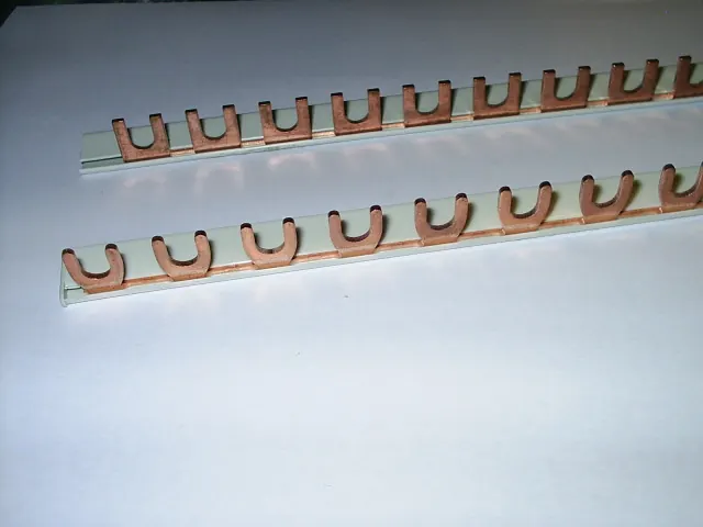
A widespread and hazardous error in DIY campervan and off-grid cabin installations is the use of automotive-grade audio fuses (ANL, MIDI, or Maxi fuses) or thermal reset breakers on large LiFePO4 battery banks. These automotive devices typically have an Ampere Interrupting Capacity (AIC) rating of only 2,000A to 6,000A.
Modern prismatic lithium iron phosphate cells have extraordinarily low internal resistance. In the event of a catastrophic direct short circuit (e.g., a dropped wrench or pinched cable), a 12V 400Ah or 48V 100Ah lithium bank can instantly discharge 15,000 to 25,000 amperes of short-circuit current. When an ANL fuse attempts to blow under 20,000 amperes, the immense energy creates an internal plasma arc that bridges the gap, completely vaporizing the plastic housing and sustaining an electrical arc fire.
As detailed in our specialized analysis on Solar Battery Fuse Sizing: Class T vs ANL, UL-listed Class T fuses are mandatory for lithium battery banks. Class T fuses feature a ceramic body packed with arc-quenching silica sand, engineered with a massive 20,000A AIC interrupting capacity at direct-current voltages up to 125V DC. They clear dead-short faults in less than 2 milliseconds, extinguishing dangerous arcs before battery terminals can explode.
8. Worked Real-World Sizing Scenarios: Campervan, Cabin & Tiny Home
To demonstrate how these calculations translate into complete off-grid power builds, review the three worked installation profiles below:
Scenario A: Campervan Kitchen Build (12V Architecture)
- Inverter Hardware: 2,000-watt pure sine wave (90% efficiency, 4,000W surge).
- Target Appliances: Single-burner induction cooktop (1,400W running) and 700W microwave.
- Peak Continuous Draw: 1,400W ÷ (12.8V × 0.90) = 121.5 DC Amperes (185A at full 2,000W).
- Battery Bank Requirement: Two 12V 100Ah LiFePO4 batteries in parallel (200Ah total), providing a combined 200A continuous BMS discharge capability.
- Conductor Specification: 2/0 AWG ultra-flexible copper welding cable (4-foot one-way run).
- Overcurrent Protection: 250A Class T fuse installed within 7 inches of positive battery busbar.
- Voltage Drop Evaluation: 0.77% (0.10V drop) under full 185A load.
Scenario B: Off-Grid Mountain Cabin (24V Architecture)
- Inverter Hardware: 2,000-watt 24V inverter/charger (92% efficiency, 4,000W surge).
- Target Appliances: Shallow-well jet pump (800W running, 2,200W starting surge) and power tools.
- Continuous & Surge Draw: 800W continuous = 36.2A; 2,200W pump starting surge = 99.6 DC Amperes.
- Battery Bank Requirement: Two 12V 100Ah LiFePO4 batteries in series (24V 100Ah nominal bank).
- Conductor Specification: 2 AWG marine-grade copper wire (8-foot one-way run).
- Overcurrent Protection: 125A Class T fuse in heavy-duty holder.
- Voltage Drop Evaluation: 1.55% (0.40V drop) during full 2,000W load.
Scenario C: Off-Grid Tiny Home Subpanel (48V Architecture)
- Inverter Hardware: 2,000-watt 48V low-frequency split-phase inverter (94% efficiency).
- Target Appliances: Refrigerator, lighting circuits, Starlink satellite dish, laptop charging stations.
- Peak Continuous Draw: 2,000W ÷ (51.2V × 0.94) = 41.6 DC Amperes.
- Battery Bank Requirement: 48V 100Ah (5.12 kWh) server-rack lithium battery with 100A continuous BMS.
- Conductor Specification: 6 AWG copper conductor in conduit (10-foot one-way run).
- Overcurrent Protection: 60A DC din-rail circuit breaker / Class T fuse.
- Voltage Drop Evaluation: 0.79% (0.41V drop) with minimal Joulean thermal losses.
Frequently Asked Questions: 2000W Inverter Current & Wiring
How long will a 100Ah lithium battery run a 2000 watt inverter?
At full 2,000-watt output, a 12V inverter draws approximately 185 DC amperes. A 12V 100Ah lithium battery contains 1,280 watt-hours of energy and has a maximum continuous discharge limit of 100 amperes. Running a 2,000-watt load on a single 100Ah battery will trigger the internal BMS overcurrent protection within seconds. If two 100Ah batteries are connected in parallel (200Ah total, delivering 200A continuous), the bank provides roughly 2,560 watt-hours. Factoring in 90% inverter efficiency and an 85% depth of discharge, runtime under a continuous 2,000-watt load is approximately 60 to 65 minutes.
Can I use a 200 amp breaker instead of a fuse for a 2000W 12V inverter?
You can use a DC-rated circuit breaker only if it is specifically engineered for renewable energy applications and carries an adequate Ampere Interrupting Capacity (AIC) rating. Standard thermal automotive breakers often have AIC ratings under 3,000A, making them dangerous on lithium battery banks that can dump 20,000A during a short circuit. Furthermore, a 200A breaker is slightly undersized for a 2,000W 12V inverter according to the NEC 125% continuous duty rule (185A × 1.25 = 231A required). A 250A Class T fuse is the industry standard for code-compliant life-safety protection.
What wire gauge do I need for a 2000 watt inverter?
The required wire gauge depends strictly on system voltage and cable length. For a 12V inverter with a one-way run under 5 feet, use 2/0 AWG or 3/0 AWG copper cable (or 4/0 AWG if the run extends to 10 feet). For a 24V inverter, use 2 AWG or 4 AWG copper wire. For a 48V inverter, 6 AWG copper wire is fully adequate. Always use 90°C or 105°C rated fine-stranded oxygen-free copper (welding or marine cable) rather than stiff solid building wire.
How many amps does a 2000 watt inverter draw with no load (idle draw)?
When turned on with zero AC appliances running, a 2,000-watt pure sine wave inverter consumes idle power (tare consumption) to keep its internal oscillator circuitry, control board, and cooling fans energized. Typical idle power ranges between 15 watts and 30 watts. On a 12-volt system, this equates to 1.2 to 2.5 DC amps continuously (29 to 60 amp-hours per day). If left energized 24/7 without solar recharge, idle tare draw alone can drain a 100Ah battery bank in less than two days.
Why does my 2000W inverter beep when I start my microwave?
The beeping indicates an instantaneous low-voltage alarm (voltage sag). When the microwave starts, its transformer draws an inductive starting surge exceeding 2,000 watts. If your 12V DC cables are undersized (e.g., 4 AWG or 2 AWG), cable connections are loose, or battery state-of-charge is low, the extreme current spike causes terminal voltage at the inverter to temporarily drop below 10.5V. Upgrading your battery cabling to 2/0 AWG and ensuring all terminal lugs are torqued to manufacturer specifications will eliminate this voltage sag.