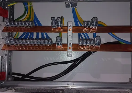
A bonded neutral inverter has its AC neutral conductor internally connected to the metal chassis and equipment ground, whereas a floating neutral inverter leaves the neutral conductor completely isolated from earth ground. The fundamental law of off-grid electrical safety is simple: an AC electrical distribution system must have exactly one neutral-to-ground bond. If you are powering standalone loads directly from the inverter’s receptacles (in an RV, mobile camper, or jobsite), the inverter must be bonded so Ground Fault Circuit Interrupters (GFCIs) can trip during a fault. However, if your inverter feeds a home subpanel or transfer switch where the neutral conductor remains continuous to the main service panel, the inverter must remain floating to prevent illegal dual-bonding loops that electrify metal conduits and trigger dangerous shock currents.
Mastering the neutral-ground relationship in off-grid solar systems requires enforcing four strict National Electrical Code (NEC) rules:
- The Single Bond Mandate (NEC 250.24(A)(5)): An electrical system must never have more than one neutral-to-ground connection on the load side of the service disconnect.
- Separately Derived System (SDS) Definition (NEC 250.30): An off-grid inverter or backup generator is legally classified as an SDS only if its transfer switch breaks (switches) the neutral conductor.
- Objectionable Ground Loop Prevention (NEC 250.6): Dual bonds force regular neutral return current to divide and travel across bare copper equipment grounding conductors (EGCs), creating shock hazards on metal appliance housings.
- GFCI Trip Reliability: In a floating neutral standalone system, an ungrounded tool fault creates no return path to the inverter’s transformer secondary, meaning GFCIs will fail to sense differential current and will not trip!
“To make your off-grid electrical setup as safe as possible, you should always bond neutral to ground inside the inverter, inside the generator, and inside every breaker panel.”
Bonding neutral to ground at multiple locations creates parallel return paths for AC current. Neutral return electricity will flow through the bare copper grounding wires, metal water pipes, and inverter chassis back to the source. Anyone touching the inverter casing under heavy household load receives an electric shock from circulating neutral voltage!
1. The Electrical Physics of Neutral and Ground
To understand why neutral-to-ground bonding causes so much confusion, we must trace how alternating current (AC) flows through an off-grid electrical circuit. In a standard single-phase 120V AC system, there are three distinct conductors:
- Hot Conductor (Ungrounded / Line): Carries current from the inverter’s high-frequency H-bridge or low-frequency transformer secondary to the load at an alternating potential of 120V RMS relative to neutral.
- Neutral Conductor (Grounded Conductor): The normal, designated return path that completes the circuit back to the inverter’s transformer center tap or neutral terminal under everyday operating conditions.
- Equipment Grounding Conductor (EGC): A non-current-carrying safety conductor (green or bare copper) bonded to metal chassis, appliance frames, and electrical boxes. Its sole purpose is to provide a low-impedance path to quickly trip a circuit breaker if a hot wire accidentally touches a metal casing.
Under normal conditions, current should only flow on the Hot and Neutral wires. Current must never flow on the Equipment Grounding Conductor. The physical purpose of the neutral-to-ground bond is to establish a zero-volt reference potential and provide a closed metallic return loop so that if a hot wire faults to the metal frame, high fault current rushes back to the source to instantly open the overcurrent protective device (breaker or fuse).
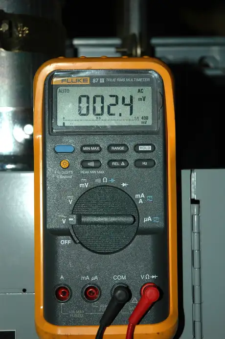
Connecting a bonded neutral inverter into an existing residential subpanel that already shares a neutral-ground bond at the main service panel creates an illegal parallel neutral return path (violating NEC 250.24(A)(5)). According to Ohm’s law (I = V / R), return current will divide proportionally between the white neutral wire and the bare copper grounding wire. Under a 20A microwave or space heater load, 8 to 10 Amps of continuous current will travel across the bare grounding conductor, electrifying the metal frame of your inverter, generator, and subpanel! Anyone with bare feet touching the chassis can suffer a fatal shock.
Select your specific off-grid installation architecture below to determine your mandatory neutral-to-ground bond configuration and applicable NEC code section.
BONDED NEUTRAL (Bond Active)
NEC 250.34 & OSHA 1926.404
Fully Functional (4–6mA Trip Active)
Keep the internal neutral-to-ground bond screw installed. Ground the inverter chassis to the vehicle frame or earth rod.
2. Deep Technical Breakdown: Bonded vs. Floating Configurations
Let us analyze the internal mechanics, circuit diagrams, and real-world failure modes of both inverter types:
| Technical Metric | Bonded Neutral Inverter | Floating Neutral Inverter |
|---|---|---|
| Internal Connection | Neutral terminal is physically jumpered to chassis ground screw via internal bonding strap. | Neutral terminal has infinite resistance (∞ Ω) to chassis ground; floats freely. |
| Voltage to Ground (Hot-to-Ground) | 120V AC (Standard RMS potential relative to earth). | Unpredictable (typically 60V–70V AC due to internal capacitive coupling filters). |
| Voltage to Ground (Neutral-to-Ground) | 0V AC (Equipotential with ground). | Unpredictable (typically 40V–60V AC phantom voltage relative to chassis). |
| Primary Use Case | Direct-connected standalone loads, portable jobsite generators, standalone RV power centers. | Grid-tied backup panels, transfer switches with unswitched neutrals, whole-house subpanels. |
| Risk if Miswired | Parallel neutral currents on ground wires if connected to an existing bonded house panel. | GFCI outlets will not trip during an accidental short to ground in standalone operation. |
Unsure whether your inverter or generator is floating or bonded? You can verify its internal architecture in under two minutes with an ordinary digital multimeter. Turn off the inverter and completely disconnect it from all AC cables and batteries. Switch your multimeter to Resistance / Continuity (Ω). Touch one probe to the round grounding pin of the AC output receptacle and touch the other probe to the wider neutral slot. If your multimeter beeps and reads 0.0 Ω (dead short), the inverter is bonded. If it reads O.L. (Open Loop / Infinite Ω), the neutral is floating!
3. The GFCI Tripping Mystery: Why Floating Neutrals Cause Failures
A Ground Fault Circuit Interrupter (GFCI) does not measure current flowing to ground; instead, it utilizes a differential current transformer (toroid sensor) that compares the current flowing out on the Hot wire against the current returning on the Neutral wire:
Trip Condition: If ΔI ≥ 4mA to 6mA for > 25 milliseconds → Open Circuit
Under research documented by Sandia National Laboratories on ground-fault blind spots (OSTI ID: 1089985), if a person touches a live hot wire while standing on damp earth, current travels through their body into the soil. For the GFCI to sense a current imbalance, that fault current must have a metallic return path back to the inverter’s transformer center tap:
- In a Bonded Neutral System: The earth ground connects to the chassis, which connects directly to the neutral. Current flows from the earth → ground rod → chassis → neutral bond → transformer secondary. The return current bypasses the GFCI toroid, creating an immediate ΔI > 5mA difference, causing the GFCI to trip within 25 milliseconds and save the person’s life!
- In a Floating Neutral System: Because the neutral is completely isolated from earth ground, there is no physical circuit connecting the soil back to the inverter transformer. When a person touches the hot wire, current cannot flow in a complete loop. While this prevents a shock in an ideal laboratory environment with a single fault, if an ungrounded tool develops a secondary internal leak, the entire metal casing becomes energized at 120V with zero GFCI protection!
4. RV & Mobile Van Grounding: The Shore Power vs. Inverter Dilemma
Mobile applications (recreational vehicles, camper vans, and overland trailers) represent the most dynamic grounding challenge in modern off-grid electrical engineering. An RV travels on rubber tires, meaning its steel chassis is completely insulated from earth ground when parked on dry pavement or asphalt.
Under the standards established by the American Boat and Yacht Council (ABYC E-11) and NEC Article 551 (Recreational Vehicles), mobile systems operate under two mutually exclusive electrical states:
State A: Plugged into RV Park Shore Power
When you plug your RV into a 30A or 50A campground pedestal, the pedestal is fed from the campground’s electrical distribution transformer, which already possesses a certified neutral-to-ground bond at the utility service entrance. In this state, the RV’s internal AC distribution panel must operate with a floating neutral. If the RV had an internal neutral-ground bond active while connected to shore power, neutral current would divide across the shore power cord’s grounding wire, creating dangerous touch voltages on the RV’s outer aluminum skin and tripping campground pedestal GFCI breakers.
State B: Boondocking / Off-Grid on Inverter Power
The moment you unplug from shore power and energize your onboard inverter, your RV becomes a self-contained island. The ground path back to the utility transformer is broken. Now, the inverter MUST establish a neutral-to-ground bond connected to the RV’s vehicle chassis! This ensures that if a wire rubs against the steel chassis inside a wall, the short circuit will instantly trip the inverter’s output breaker rather than energizing the entire RV body.
5. The Generator “Open Ground” Error & The Edison Bonding Plug
Thousands of off-grid homeowners and RV owners encounter this frustrating scenario: they purchase a top-tier inverter generator (such as a Honda EU2200i, Predator 3500, or Champion) to recharge their off-grid battery bank during winter. When they plug their RV or battery charger into the generator, the RV’s onboard Electrical Management System (EMS) or surge protector displays a flashing red error code: “OPEN GROUND” and refuses to allow AC power to pass through!
Why does this happen? Most portable generators ship from the factory with a floating neutral to comply with OSHA jobsite requirements when connected to transfer switches. Because the neutral and ground pins on the generator’s 120V outlets are isolated, the RV’s smart surge protector detects infinite resistance between neutral and ground and flags an open ground fault.
You can resolve generator “open ground” lockouts safely in under 5 minutes without opening the generator case. Take a standard 3-prong 15A male replacement plug (Edison plug). Inside the plug, install a 14 AWG insulated copper jumper wire connecting the silver neutral screw directly to the green ground screw. Leave the brass hot screw completely disconnected! Plug this bonding plug into one of the generator’s spare 120V outlets. It instantly bonds neutral to ground for all parallel outlets on the generator, allowing your RV surge protector to see a valid ground reference and pass clean AC power. (Caution: Only use this plug when the generator is powering standalone loads or an RV directly; NEVER use a bonding plug when the generator feeds a house panel with an unswitched neutral!)
6. Sizing Equipment Grounding Conductors (NEC 250.122 & Earth Impedance Math)
A common misconception among beginner solar builders is that driving an 8-foot copper ground rod into the soil provides adequate protection to trip a circuit breaker. Soil resistance is far too high to ever trip an AC overcurrent protective device!
Consider the fundamental physics governed by Ohm’s Law (I = V / R). A properly installed residential ground rod typically achieves an earth contact resistance between 15 Ω and 25 Ω under ideal moist soil conditions:
A fault current of only 4.8 Amps flowing through the dirt will NEVER trip a standard 15A or 20A circuit breaker! The breaker will remain closed indefinitely while 4.8 Amps heats the soil, creating a continuous electrocution hazard for anyone walking nearby. This mathematical reality proves why a dedicated, low-impedance metallic Equipment Grounding Conductor (EGC) sized per NEC Table 250.122 is mandatory:
| Inverter Continuous Output Breaker Rating | Minimum Copper Equipment Grounding Conductor (EGC) | Minimum Conductor Ampacity Standard |
|---|---|---|
| 15 Amps | 14 AWG Copper | NEC Table 250.122 Standard |
| 20 Amps | 12 AWG Copper | NEC Table 250.122 Standard |
| 30 Amps (3,600W Inverter) | 10 AWG Copper | NEC Table 250.122 Standard |
| 60 Amps (6,000W Inverter) | 10 AWG Copper | NEC Table 250.122 Standard |
| 100 Amps (12 kW Multi-Inverter Stack) | 8 AWG Copper | NEC Table 250.122 Standard |
- Step 1: Perform De-energized Resistance Audit: Disconnect all AC input and output cables. Set a digital multimeter to Ohms (Ω). Measure resistance between the AC neutral terminal and the metal chassis ground. Record whether the unit reads 0.0 Ω (bonded) or O.L. (floating).
- Step 2: Inspect Transfer Switch Neutral Conductor: Verify whether your manual transfer switch or subpanel switches the neutral wire. If the neutral busbar is continuous back to the main panel, the inverter MUST be configured as floating neutral.
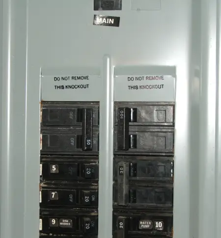
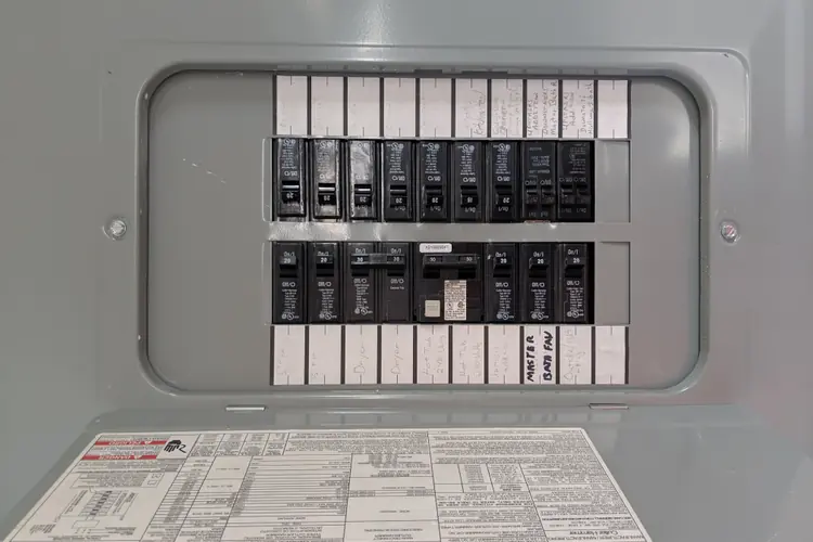
- Step 3: Verify Subpanel Neutral-Ground Separation: Open the off-grid subpanel. Confirm that the green bonding screw is REMOVED from the neutral busbar, and that the neutral bus is insulated from the metal enclosure.
- Step 4: Energize Inverter and Verify Voltage Potentials: Power on the inverter under no load. With a calibrated AC voltmeter, measure:
• Hot to Neutral: Must read 120V ± 3V AC.
• Neutral to Ground: Must read 0V AC (if bonded) or 0V–3V AC (if connected to an external bonded subpanel).
• Hot to Ground: Must read 120V ± 3V AC. - Step 5: Test Downstream GFCI Receptacles: Plug a commercial 3-prong GFCI receptacle tester into every protected branch circuit. Verify that the correct wiring indicator lights illuminate, press the test button, and confirm the GFCI trips within 25 milliseconds.
- Step 6: Execute Objectionable Current Clamp Test: Under full operating household load, place a sensitive AC current clamp meter around the bare equipment grounding conductor (EGC). The clamp meter must read 0.00 Amps. Any reading above 0.2A indicates an illegal dual-bond ground loop that must be resolved immediately!
7. Frequently Asked Questions (PAA Search Schema)
Why does my generator trip my RV’s GFCI outlets?
Most portable inverter generators ship with a floating neutral. Modern RV electrical management systems (EMS) or surge protectors inspect the incoming power and detect the floating neutral as an “Open Ground” error, refusing to allow power into the RV. The solution is to plug an inexpensive neutral-ground bonding plug (which connects the neutral pin to the ground pin with a jumper) into one of the generator’s spare 120V outlets.
Can I convert a floating neutral inverter into a bonded neutral inverter?
Yes. On many standalone inverters, manufacturers provide a designated internal bonding screw or jumper terminal clearly marked on the chassis. Installing the screw bonds the neutral terminal directly to the metal frame. If the manufacturer does not support internal bonding, you can install an external bonding jumper inside an external junction box before feeding standalone receptacles.
What happens if you have two neutral-to-ground bonds in the same house?
Having two neutral-to-ground bonds violates NEC 250.24(A)(5). It creates parallel return paths for everyday AC current. Return current will split between the white neutral wire and the bare copper equipment grounding wires. This electrifies metal electrical panels and appliance frames, causes humming noise on audio/video equipment, and continuously trips GFCI and AFCI breakers.
Why do I measure 60 volts from neutral to ground on my floating inverter?
This is called “phantom voltage.” Modern high-frequency inverters incorporate electromagnetic interference (EMI) filtering capacitors connected between Hot-to-Chassis and Neutral-to-Chassis. When the neutral is floating, these capacitors act as a capacitive voltage divider, centering the chassis potential halfway between the 120V AC rail, resulting in a 60V reading on a high-impedance digital multimeter. Once you load the circuit or properly bond the system, this phantom voltage disappears.
Does a floating neutral generator need a ground rod?
According to OSHA 1926.404 and NEC 250.34, a portable generator does NOT require a grounding electrode (ground rod) if it only supplies equipment plugged directly into the receptacles mounted on the generator itself, and the metal non-current-carrying parts are bonded to the generator frame.
Should an off-grid cabin subpanel have its neutral bonded?
No. If the subpanel is fed from an inverter where the neutral-ground bond already exists (either inside the inverter or at an upstream master disconnect), the subpanel MUST keep its neutral and ground busbars isolated. The green bonding screw in the subpanel must be removed.