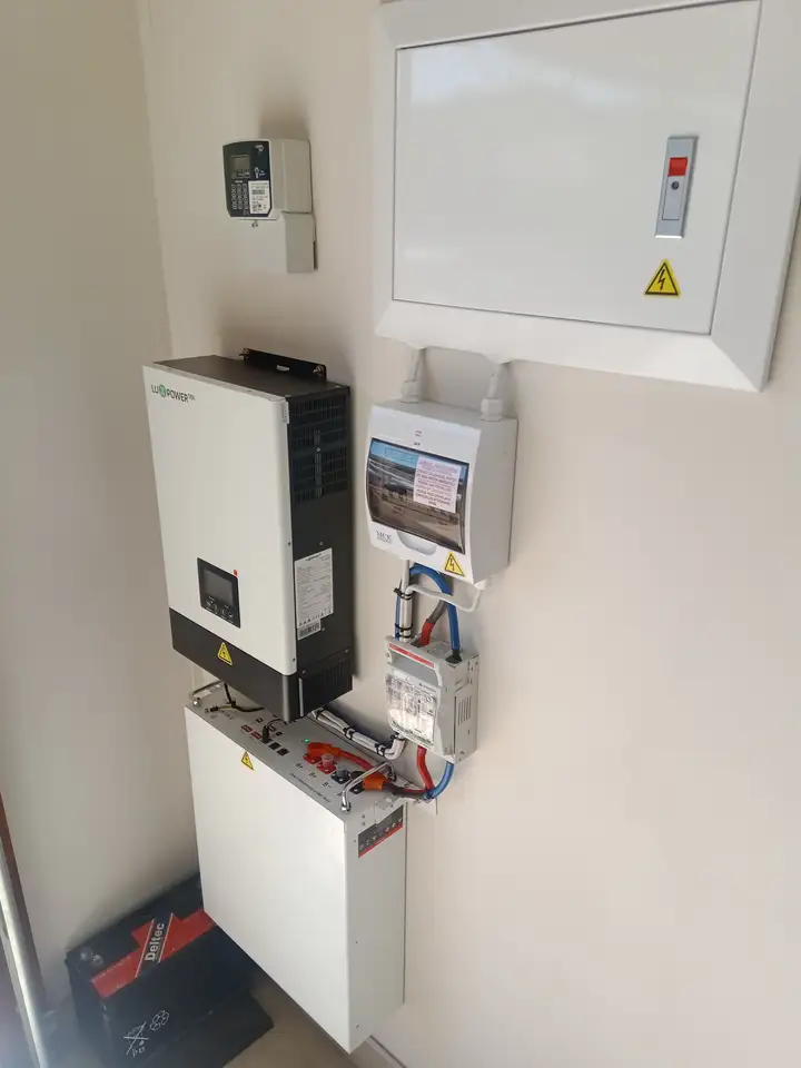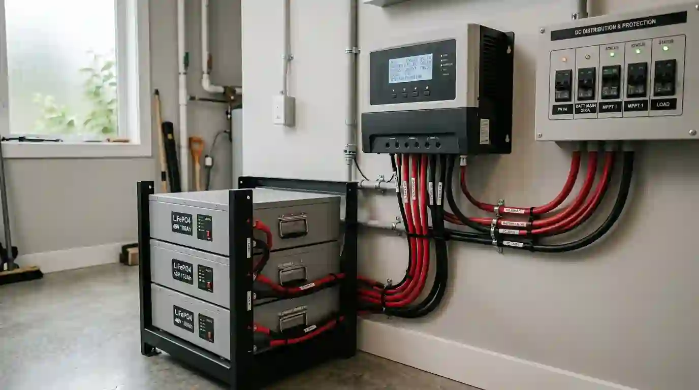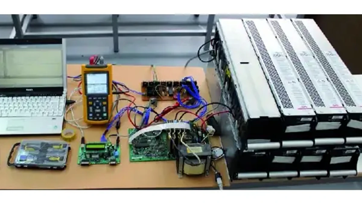
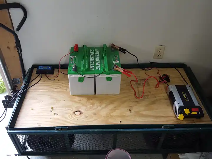
Featured image: Laboratory power equipment illustrating battery-system components; this photograph is not a wiring diagram. Photo by Mustafa Engin on Wikimedia Commons (CC BY 4.0).
The 12V, 24V, and 48V labels refer to nominal battery-bank and inverter DC voltage. Choose a system around the loads, compatible equipment, current, cable layout, and manufacturer limits. Higher voltage reduces current for the same power; lower voltage can make a small system with native 12V appliances simpler. This guide compares the tradeoffs, shows the calculations and explains which equipment limits to check before buying.
1. 12V vs 24V vs 48V Solar: Quick Comparison
These voltage labels describe the battery bank and inverter DC input. They do not describe the solar panel string voltage or the inverter’s AC output. A 48V battery system does not automatically provide 240V AC: the inverter must support the required output voltage, frequency and phase arrangement.
| Planning factor | 12V system | 24V system | 48V system |
|---|---|---|---|
| Typical fit | Small campers, native 12V appliances and modest AC loads | Cabins, sheds and medium inverter loads | Larger inverter loads and expandable home storage |
| Battery current at 2,400W AC, 92% efficiency | 217.4A at 12.0V | 108.7A at 24.0V | 54.3A at 48.0V |
| Common LiFePO4 nominal voltage | 12.8V (4 cells in series) | 25.6V (8 cells in series) | 51.2V (16 cells in series) |
| 100Ah battery nominal energy | 1.28kWh at 12.8V | 2.56kWh at 25.6V | 5.12kWh at 51.2V |
| Powering 12V accessories | Check appliance input range | Usually needs a DC-DC converter | Usually needs a DC-DC converter |
For any comparison, check the actual inverter DC input range and continuous and surge ratings, the battery and BMS current limits, and the required charging equipment. Manufacturer guidance may use VA rather than watts. There is no universal AC-watt threshold for choosing among nominal battery voltages.
For example, 2,400 ÷ (24 × 0.92) = 108.7A. At an actual battery voltage of 22V, the same estimate rises to 118.6A. Use the equipment’s operating range when checking maximum current; 92% is an example assumption, not a guaranteed efficiency at every load.
Read these four units before comparing equipment
Watts (W) measure power at one moment. Watt-hours (Wh) measure energy used over time. Amps (A) measure current in a wire. Volts (V) describe the electrical potential difference. A 1,000W kettle used for six minutes needs about 100Wh. It still needs an inverter that can supply its full 1,000W while it runs.
Amp-hours only describe stored charge. Pair them with voltage to compare energy. Also keep watts and volt-amps (VA) separate: a motor can place a larger VA demand on an inverter than its real-power watts suggest. Check both ratings when the inverter manual lists them.
Quick answer: Start with the exact loads and equipment you need to support. Compare 12V, 24V and 48V only where compatible batteries, inverters and charging equipment are available; then check voltage range, continuous and surge ratings, battery and BMS current limits, conversion losses, and installation constraints. A higher nominal voltage can reduce current for the same power under comparable conditions, but it does not by itself establish equipment or system suitability.
2. When a 12V Solar System Makes Sense
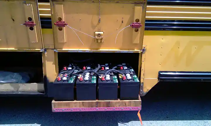
A 12V battery bank is a practical option when lights, a fridge, fans and a water pump already use compatible 12V DC power. Keeping those loads on DC can avoid inverter standby consumption. Check each appliance’s allowed input range because a battery’s charging voltage is higher than its nominal label.
Consider a camper with a 600W AC load. At 12V and 92% inverter efficiency, the inverter draws about 54.3A before other DC loads are added. At 2,000W, that estimate becomes 181.2A. This explains why a system that works well for laptops may need substantial changes for an induction cooker.
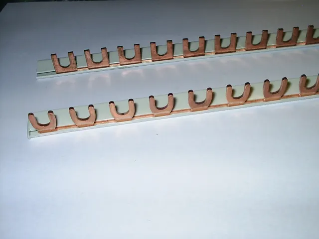
Check the whole path that carries current. That means the battery, its battery management system (BMS), cables, terminals, busbars and fuses. A high amp-hour rating does not prove that a battery can power a large inverter.
To charge from a vehicle, match the charger to the battery and alternator. Check how much current the alternator can spare. Do not assume a lithium house battery can connect straight to it.
3. When a 24V Solar System Is a Good Fit

A 24V off-grid system is worth comparing for a cabin or workshop with medium AC loads. At equal power and efficiency, doubling battery voltage halves the calculated current. That can ease cable routing and reduce voltage drop without committing to a larger battery system.
A 2,000W AC load draws about 90.6A at 24V and 92% efficiency. The battery must also support simultaneous DC loads and inverter startup demand. A refrigerator or saw motor can require considerably more power during starting than while running.
Compare a native 24V battery with a series bank of manufacturer-approved 12V batteries. Include any required monitoring, interconnects and a 24V-to-12V converter in the budget. One correctly sized converter can supply several fused 12V branches; a separate converter is not necessarily required for every appliance.
4. When a 48V Solar System Is Worth Choosing
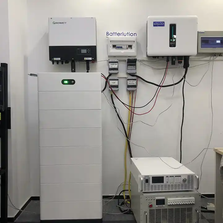
A 48V battery bank becomes attractive as inverter power increases. For a 5,000W AC load at 48V and 92% efficiency, the estimate is 113.2A, compared with 452.9A at 12V. Lower current can make a high-power design easier to build, although every component still needs to be sized for the actual installation.
Many residential storage products use 51.2V LiFePO4 modules sold as “48V” batteries. Match the battery’s operating and charging ranges to the inverter. A rack enclosure, CAN port or RS485 connector alone does not guarantee compatible battery communications.
Check the inverter’s continuous watts, surge duration, idle consumption and AC output arrangement. A small cabin can waste a meaningful share of its daily energy keeping an oversized inverter awake. Higher voltage does not automatically mean lower total energy use.
5. Cable Size, Voltage Drop and Resistive Losses
Current flowing through cable resistance causes voltage drop and heat. The basic relationships are voltage drop = current × resistance and power loss = current² × resistance. Include the positive and negative conductors when calculating total circuit length.
| Quantity | 12V | 24V | 48V |
|---|---|---|---|
| Ideal current, before inverter losses | 200A | 100A | 50A |
| Voltage drop | 1.00V | 0.50V | 0.25V |
| Resistive cable loss | 200W | 50W | 12.5W |
In this simplified comparison, the 48V cable loss is 93.75% lower than at 12V. This is not a claim of 93.75% better system efficiency. It assumes identical cable resistance; changing cable size changes the result. A constant-power inverter also draws more current as its input voltage falls.
Wire size depends on more than voltage drop. Check how much current the wire can carry, its length and type, and the heat around it. The terminals and cable route matter too. Two wires in parallel do not always give twice the usable current rating. Follow the rules for that cable layout.
See the manufacturer’s DC wiring guidance for equipment-specific cable selection considerations. Apply the electrical code adopted for your location rather than assuming one edition governs every installation.
Worked wire example: 2,400W on a 24V battery bank
Ampacity means the current a wire can carry under stated heat and installation conditions. It is a separate check from voltage drop. Here is a worked screening example, not a final cable schedule.
- Set the inputs: use 2,400W AC, 92% efficiency and an assumed lowest operating voltage of 22V. The cable run is 10 feet each way, so the loop is 20 feet.
- Estimate current: 2,400 ÷ (22 × 0.92) = 118.6A. For a real inverter, use its rated maximum input current if the manual supplies it.
- Apply the stated design factor: for this example, assume the applicable circuit rule calls for 125%. Then 118.6 × 1.25 = 148.2A. That factor is not a universal rule for every battery circuit.
- Screen the cable: a 1/0 AWG copper conductor has a 150A base value in the cited 75°C table. A 2/0 conductor has a 175A base value. The first has little margin if any correction is needed.
- Check drop: using the illustrative 75°C copper constant K = 12.9 ohm-circular-mils per foot, drop = 2 × K × one-way feet × amps ÷ circular-mil area.
| Candidate | 75°C base ampacity | Area, circular mils | Drop at 118.6A | Share of 22V |
|---|---|---|---|---|
| 1/0 AWG copper | 150A | 105,600 | 0.290V | 1.32% |
| 2/0 AWG copper | 175A | 133,100 | 0.230V | 1.04% |
The Southwire copper conductor table lists those base ampacities. The table assumes defined installation conditions; it is not a recommendation to use that product in every battery enclosure. Check cable listing, strand type and terminal compatibility.
Next, apply heat and grouping corrections, check the terminal temperature rating, and coordinate the fuse. A 90°C insulation label does not automatically allow use of the 90°C ampacity at a 75°C terminal. The 2/0 candidate provides more base margin here, but neither candidate is approved until those checks pass.
Doubling the one-way run doubles the calculated drop with the same cable. A loose lug adds resistance too. For example, a 0.001-ohm connection carrying 120A dissipates 14.4W at that small joint. Use the specified lug and torque; do not try to solve a poor connection by fitting a larger fuse.
Installation handoff: record maximum input current, minimum input voltage, cable route, conductor type, temperature corrections, terminal rating and the chosen protective device. Give that list to the installer so the final design can be checked.
6. MPPT Charge Controller Sizing and Panel Voltage
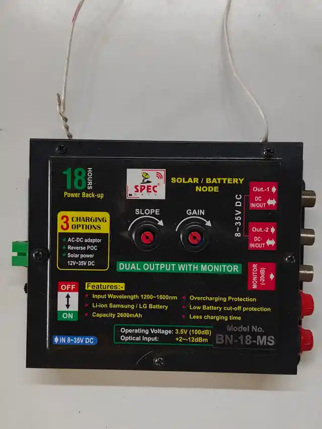
An MPPT solar charge controller has two sides. The PV side receives power from the panels. The battery side sends charge to the bank. Each has its own current and voltage limits.
As an illustrative output calculation, a controller supplying 60A at 14.4V delivers 864W to the battery. At 28.8V it delivers 1,728W, and at 57.6V it delivers 3,456W. These are multiplication examples, not permission to connect those array sizes to any 60A controller. The controller must support the selected battery voltage and the manufacturer’s PV limits.
- Check the array’s cold-weather open-circuit voltage against the controller’s maximum PV input voltage.
- Check the allowed PV short-circuit current, operating current and array wattage separately.
- Confirm sufficient PV operating voltage for startup and charging in hot conditions.
- Check allowable overpaneling and clipping behavior in the exact model’s manual.
Panel strings commonly operate at a higher voltage than the battery. Rewiring panels in series changes string voltage; it does not change the battery’s nominal voltage. For the layout calculation, see our solar panel series-versus-parallel guide.
A real controller example: SmartSolar MPPT 150/60
The Victron 150/60 specification table lists 60A maximum battery current and nominal PV power of 860W at 12V, 1,720W at 24V and 3,440W at 48V. It also lists a 50A PV short-circuit limit, 150V absolute cold-weather maximum and 145V startup/operating maximum. These limits apply to this model, not every 60A controller.
Cold-weather string calculation
Assume a panel has 40V open-circuit voltage at 25°C and a voltage temperature coefficient of −0.28% per °C. At a design minimum of −10°C, the temperature change is 35°C. Estimated cold voltage per panel is 40 × [1 + (0.0028 × 35)] = 43.92V.
Three panels in series give 131.76V; four give 175.68V. The four-panel string exceeds this controller’s limit. The three-panel result still needs checks for the panel’s stated tolerances and the required local design method. Do not use a fixed winter percentage in place of the panel coefficient and site temperature.
Series adds voltage. Parallel strings add current. If each string has 10A short-circuit current, three strings give 30A before applicable corrections. Also check hot-weather operating voltage, connector current, cable protection and battery charge-current limits. A controller that clips excess power does not waive its voltage or short-circuit-current limits.
7. Battery Capacity: Series, Parallel and Usable kWh
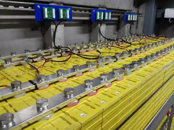
Compare battery capacity in watt-hours rather than amp-hours alone: nominal energy (Wh) = nominal voltage × amp-hours. A 51.2V 100Ah pack contains 5,120Wh nominally, while a 12.8V 100Ah pack contains 1,280Wh.
Four matching 12.8V 100Ah batteries contain 5.12kWh in total whether arranged as an approved 51.2V 100Ah series bank or a 12.8V 400Ah parallel bank. Rewiring does not create additional stored energy. Usable AC energy is lower after the permitted depth of discharge, inverter losses and other consumption.
Suppose you need 2kWh of AC energy for one day without charging. Assume you can use 80% of the battery and the inverter is 92% efficient. You need 2 ÷ (0.80 × 0.92) = 2.72kWh of nominal storage. Add reserve and any DC loads. Daily energy helps size the battery and panels. It does not set a fixed system voltage.
Series and parallel permissions are model-specific. There is no universal four-battery parallel limit. For example, Victron’s Lithium Smart design guide describes configurations with more than four parallel batteries for that product family. Follow your own battery manual, including matching, balancing and protection requirements.
Our battery bank wiring guide explains the layout concepts. Do not connect lithium batteries in series unless their manufacturer explicitly allows it.
Compare equal energy, then compare equal power
| Layout | Bank rating | Nominal energy | What changes |
|---|---|---|---|
| Four in parallel (4P) | 12.8V, 400Ah | 5.12kWh | Higher shared bus current |
| Two series pairs in parallel (2S2P) | 25.6V, 200Ah | 5.12kWh | Series approval and balanced parallel paths needed |
| Four in series (4S) | 51.2V, 100Ah | 5.12kWh | Every battery must permit four in series |
If each battery permits 100A discharge, a series string still has a 100A limit; series wiring does not add current ratings. Parallel strings can share load, but uneven cable paths or one BMS opening can overload the remaining string. Use the maker’s approved layout rather than assuming perfect current sharing.
Useful energy example: a 5.12kWh bank at 80% usable depth and 92% inverter efficiency supplies about 3.77kWh AC. A steady 500W load would run for about 7.5 hours under those assumptions. Cold, ageing, standby power and other loads can shorten this estimate.
For expansion, ask whether new and older packs may be mixed, how many parallel units are allowed, and whether communication requires a master battery. Match charge settings and state of charge before connecting packs as directed by the manufacturer. Never mix chemistries just because the voltage labels match.
8. Inverter Surge Power and Battery Voltage Sag
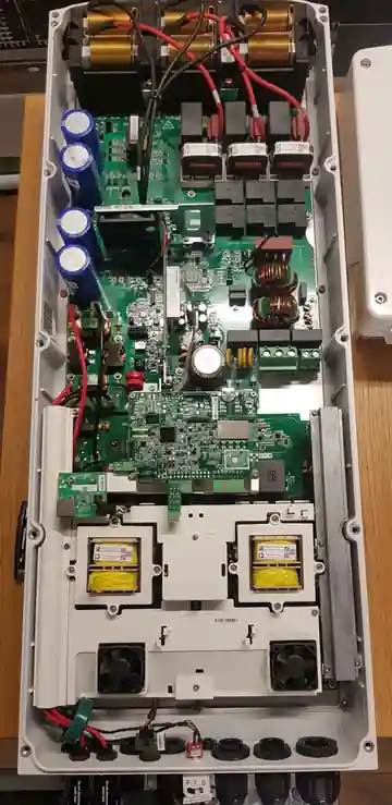
Motor startup is a separate design check from continuous power. Read the motor or appliance starting requirements and the inverter’s surge rating with its allowed duration. A marketing “peak watts” figure without a duration is not enough to confirm that a pump will start.
For a hypothetical 4,500W AC surge and 92% efficiency, current is approximately 407.6A at 12V, 203.8A at 24V or 101.9A at 48V. These are estimates at fixed voltages. Battery resistance, BMS limits and cable drop affect the actual transient behavior.
Higher voltage reduces the current needed for a given power, but cannot guarantee that a motor starts. A larger series bank may also have different internal resistance and energy capacity. Compare compatible batteries at the capacity and discharge rating you actually intend to buy.
Worked motor-starting check
Suppose a tool draws 1,200W while running. Its documented starting demand is 4,500W for two seconds, and other loads use 300W. The inverter must supply 1,500W continuously and 4,800W during the start. A 6,000W peak rating that lasts only 20 milliseconds would not establish that it can do this.
At 22V and an assumed 90% surge efficiency, battery current for the start is 4,800 ÷ (22 × 0.90) = 242.4A. At 44V it is 121.2A. Check the battery’s pulse rating for at least the required duration, not only its continuous rating. Motor power factor and inverter VA limits must also fit.
Why a simple surge estimate can still miss a shutdown
For a simplified constant-power model, let a 24V source have 0.010 ohm total resistance in the battery, cables and connections. It must supply 5,333W DC to support that 4,800W AC start at 90% efficiency. The circuit must satisfy P = I × (24 − I × 0.010).
The lower-current solution is about 247.8A. The inverter sees about 21.52V, not 24V. If its configured cutoff is 22V, this example predicts a low-voltage problem. A simple 5,333 ÷ 24 calculation gives only 222.2A and misses part of the sag.
This is a steady electrical model of an assumed start. It is not a motor test or a battery pulse simulation. Actual behavior also depends on BMS timing, the inverter’s control, battery state of charge and motor acceleration. It shows why a larger inverter alone may not fix a startup fault.
- Verify the load’s starting VA or watts and duration.
- Check inverter overload capacity at that duration.
- Check battery and BMS pulse limits, including low state of charge.
- Check loaded voltage, cable drop and the fuse’s time-current curve.
9. Fuse Ratings and Battery Fault Protection
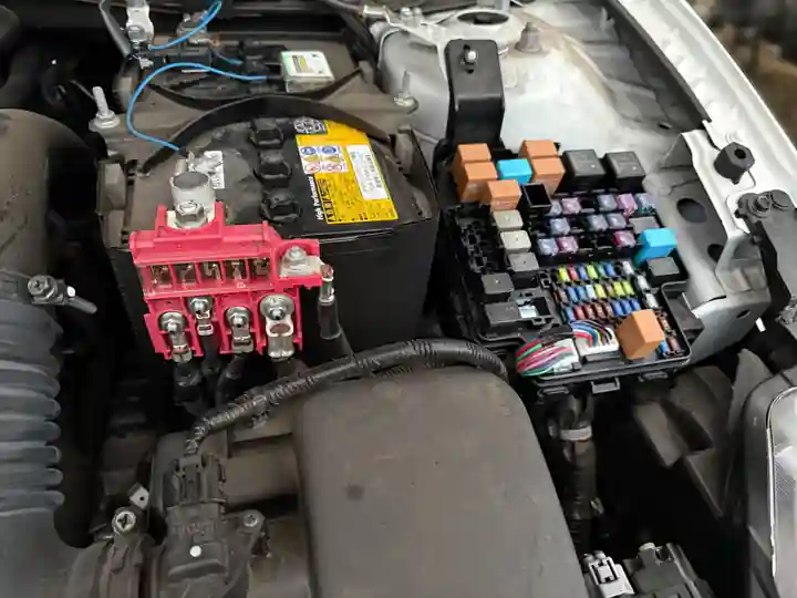
A battery fuse has several ratings. Check its current rating, DC voltage limit and speed of response. Also check its interrupt rating: the largest fault current it can safely stop under stated conditions. This is not the same as the normal current printed on the fuse.
Class T and MRBF describe different fuse designs, not universal suitability for a battery voltage. Check the exact part and holder against the battery’s prospective short-circuit current and maximum charging voltage. A device rated for 58V DC should not be assumed suitable for a bank that can reach 58.4V.
Place the fuse where the equipment manual and local rules require it. Match its rating to the wire and load. A BMS does not remove the need for external fuses or breakers where required. See the DC wiring reference for fuse selection topics. Confirm each rating in the chosen fuse’s datasheet.
Read the exact fuse ratings
| Exact product | Current rating | Maximum DC voltage | Published DC interrupt rating |
|---|---|---|---|
| Blue Sea 5190 MRBF | 300A | 58V | 10,000A at 14V; 5,000A at 32V; 2,000A at 58V |
| Blue Sea 5118 Class T | 250A | 125V | 20,000A at 125V |
These are examples for reading a datasheet, not interchangeable fuse choices. Check the current page, the supplied device label and its holder. A higher interrupt rating does not make an oversized fuse suitable for a smaller cable.
Two separate reasons a fuse can fail the selection check
Assume a battery manufacturer provides 8,000A prospective fault current at the fuse location. The 5190’s published 2,000A rating at 58V does not cover that fault. Separately, if maximum charging voltage is 58.4V, its 58V maximum is also too low. Passing one check would not fix the other.
The cited Class T example has a higher voltage and interrupt rating. But its 250A current rating still needs to match the actual cable and load. It is not a suitable conclusion to attach that fuse to the 175A base-ampacity wire example above.
Check five items together: maximum DC voltage, prospective fault current, conductor protection, normal operating current and the time-current curve. The last shows how long a fuse takes to open at a given overload. It helps test whether a motor start can pass without losing cable protection. Use manufacturer fault-current data or a qualified assessment; do not test fault current by shorting a battery.
10. Grounding, Bonding and AC Compatibility
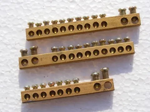
Do not assume that battery negative should always be bonded to earth, or that it should always float. The correct arrangement depends on inverter design, mobile or stationary use, and local requirements. AC neutral-to-earth bonding and protective-earth connections also need their own checks.
A move from 12V to 48V does not remove the need for grounding. Use the inverter maker’s wiring diagram. Have a qualified person handle panel work, transfer switches and work that needs a permit.
Three connections with different jobs
- Protective earth (equipment ground): connects exposed metal cases to the protective system. It should not carry normal load current.
- AC neutral-to-earth bond: establishes the required source reference in a bonded AC system. Its location can change with the source and transfer arrangement.
- DC negative bond: connects battery negative to the grounding system only where the equipment design and local rules require or permit it.
Some inverter/chargers use a relay to change their neutral bond when switching between inverter power and shore or generator power. Adding a permanent extra link can create unwanted current paths. Check every operating mode in the manufacturer’s grounding guidance.
Live conductor touches metal case → protective-earth conductor → designated source bond → source winding. This low-impedance path allows the protective device to respond. This is a concept sketch, not a connection diagram for your inverter.
A ground rod alone does not replace the protective wire. An RCD or GFCI detects certain current leaks and trips the circuit. Have the installer check the bonds and test this protection on inverter power and on the external supply.
11. LiFePO4 Charging Voltage and BMS Settings
Nominal voltage is a label, not a fixed reading. A common LiFePO4 cell is rated at 3.2V. Four in series give 12.8V; eight give 25.6V; sixteen give 51.2V. Other cell types and counts have different voltage ranges.
Use the battery manufacturer’s charge profile, low-temperature charging limits and discharge settings. Do not treat a generic voltage chart as a precise state-of-charge meter, or a BMS emergency cutoff as a normal operating target. Where specified, configure the inverter to stop discharging before the BMS disconnects the pack.
Check every charger: solar, mains and vehicle. Each must use the right charge profile. If the BMS sends limits to the inverter, check their settings and software versions too.
12. Compare Complete System Costs
Ask for quotes that serve the same loads and store the same usable energy. Match the surge and solar input needs too. A 3kW inverter and a 5kW all-in-one unit do different jobs. Their price gap does not show the cost of battery voltage alone.
| Item | What to compare |
|---|---|
| Inverter or inverter/charger | Continuous watts, surge duration, AC output, idle consumption and certification |
| Battery storage | Usable kWh, continuous and peak discharge limits, warranty and supported expansion |
| Solar charge controllers | PV input limits, battery voltage support and controller count |
| DC distribution | Cables, lugs, busbars, enclosures, fuses and disconnects |
| Additional hardware | DC-DC converters, communications, monitoring and mounting |
| Installed cost | Panels, racking, AC work, permits, delivery, taxes and labor |
Higher battery voltage can reduce cable requirements and may suit an integrated inverter/charger. A small native-12V installation can still cost less overall. Obtain current local quotes; this guide does not treat unsourced retail estimates as verified market prices.
Battery price snapshot at equal nominal energy
The following manufacturer-page prices were checked on October 4, 2026, in US dollars. Each row provides 5.12kWh nominal energy. Unit prices are multiplied without bundle discounts, shipping or tax. These products have different features, so the table compares purchase cost per kWh, not equal performance or a brand recommendation.
| Battery product | Quantity and layout | Unit price | Bank subtotal | Cost per nominal kWh |
|---|---|---|---|---|
| LiTime 12V 100Ah Classic | 4 × 12.8V 100Ah, parallel for 12V | $302.39 | $1,209.56 | $236.24 |
| LiTime 24V 100Ah Group 31 Xtra-Mini Smart | 2 × 25.6V 100Ah, approved parallel for 24V | $620.99 | $1,241.98 | $242.57 |
| LiTime 48V 100Ah ComFlex rack battery | 1 × 51.2V 100Ah | $1,099.99 | $1,099.99 | $214.84 |
The 48V listing showed out of stock when checked. Its listed price is not a promise of availability. Recheck prices and parallel permissions before ordering. The 24V model adds Bluetooth and low-temperature protection; the rack model has different communications and mounting. Check required system certifications too—marketing claims or shipping tests are not proof that a complete installation is approved.
A transparent full-system budget exercise
For a 2,400W AC design target, start with those battery subtotals. Then enter current quotes for compatible inverter, MPPT, cables and protection. The numbers below are illustrative allowances, not verified product quotes. They show the addition and the cost sensitivity without pretending to specify a complete build.
| Cost line | 12V | 24V | 48V |
|---|---|---|---|
| Battery subtotal from linked pages | $1,209.56 | $1,241.98 | $1,099.99 |
| Inverter allowance | $700 | $700 | $700 |
| MPPT allowance | $600 | $400 | $300 |
| DC cable, protection and distribution allowance | $500 | $350 | $300 |
| Illustrative subtotal | $3,009.56 | $2,691.98 | $2,399.99 |
Panels, mounting, AC distribution, converters, tax, freight, permits and labor are excluded. The allowances also need validation against each selected product’s ratings. Do not use this subtotal as an installed-price quote.
Under these assumptions, the 48V subtotal is $609.57 below 12V and $291.99 below 24V. If its inverter costs $400 more, that advantage over 24V disappears. This is why a complete quote matters more than saying “48V is always cheaper.”
Battery Current Calculator: Compare All Three Voltages
13. How to Choose Your Off-Grid Battery Voltage
- List simultaneous loads. Separate running watts, starting demand and native DC appliances.
- Calculate daily energy. Multiply each appliance’s watts by hours of use, then size battery autonomy and solar production separately.
- Compare compatible inverters. Check DC operating range, continuous output, surge duration and standby losses.
- Check the battery and BMS. Confirm discharge current, charging limits and approved series/parallel configurations.
- Plan the layout. Keep battery-to-inverter cables short where practical and assess both ampacity and voltage drop.
- Price the complete system. Include converters for DC appliances and the likely cost of future expansion.
Start with our off-grid solar sizing calculator to estimate energy and array requirements. Use the results alongside equipment manuals when selecting a battery voltage.
A final compatibility checklist for 12V vs 24V vs 48V solar
Before buying, write down the battery’s full charge voltage, normal discharge range, usable kWh and current limits. Beside them, write the inverter’s DC range, rated input current, output watts and surge duration. Check the MPPT input limits against the actual string design. A mismatch in any one of these can stop a system from working even if its energy estimate looks correct.
For a modest DC-only setup, also price the option of leaving the inverter off most of the day. An assumed 20W idle draw over 24 hours consumes 480Wh. That is nearly one quarter of a 2kWh daily budget. Use the chosen inverter’s measured or specified idle demand for your own estimate.
14. Three Illustrative Design Scenarios
Camper with mostly 12V appliances
A camper running DC lights, a fridge and occasional laptop charging may benefit from a 12V bank and a modest inverter. Check the fridge’s daily energy use and alternator charging compatibility. An induction cooker or electric heater can change the power requirement substantially.
Workshop with a saw or compressor
A workshop might compare 24V and 48V even when its running load is below 3kW. Motor starting demand, battery discharge limits and cable routing may matter more than daily energy consumption. Confirm the starting load before selecting the inverter.
Cabin with larger storage and household loads
A cabin needing several kilowatts at once may favor 48V equipment and compatible storage modules. Check winter solar production, overnight energy use and backup charging. A 48V label does not establish that the system can power every appliance simultaneously.
15. Frequently Asked Questions
Is 48V solar more efficient than 12V?
For the same power, higher battery voltage reduces current and can reduce cable losses. Total efficiency also depends on wire size, inverter loading, standby consumption and DC-DC conversion. Compare the complete system rather than voltage alone.
Can I run 12V appliances from a 24V or 48V battery?
Yes, with a suitable DC-DC step-down converter sized for the combined continuous and startup loads. Do not tap one battery in a series bank to supply 12V loads, because that creates imbalance.
Does a 48V 100Ah battery store more energy than a 12V 100Ah battery?
Yes. For common LiFePO4 packs, 51.2V × 100Ah = 5.12kWh, while 12.8V × 100Ah = 1.28kWh. Compare nominal and usable watt-hours, not amp-hours alone.
Can I upgrade from 12V to 24V or 48V later?
Possibly, but the inverter usually needs to match the new battery voltage. Check battery series permissions, charge controller support, DC appliances and protective devices. Solar panels may be reusable after checking string voltage and current limits; rewiring is not automatically free or compatible.
Can a 12V alternator charge a higher-voltage house battery?
A suitable step-up DC-DC charger can do this. It must support the vehicle and battery chemistry, and its input current must fit the alternator and wiring capacity.
Which system voltage is best for a small off-grid cabin?
Choose from simultaneous power, motor startup demand, cable distance and compatible equipment. A small DC-focused cabin may suit 12V; compare 24V or 48V as inverter demand grows. Daily kWh alone does not decide the voltage.
16. Choose Voltage Around Your Loads and Equipment
The useful distinction in 12V vs 24V vs 48V solar is how each voltage fits your loads and equipment. Start with 12V for a modest system built around compatible DC appliances, compare 24V for medium inverter demand, and consider 48V for larger loads or expansion.
Before ordering, check the battery’s capacity and current limits. Check the inverter’s surge rating and the MPPT input limits. Then review the cable layout. No one voltage is best for every build.
Continue with our inverter sizing guide and charge controller sizing guide.
The calculations are worked planning examples, not results from a physical installation test. Linked manufacturer pages support the product-specific figures. Manufacturer-page prices were checked on October 4, 2026; technical specifications can vary by model, so verify current manuals and installation requirements before purchase. Final equipment selection must use the current manuals and the code adopted at the installation site.