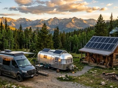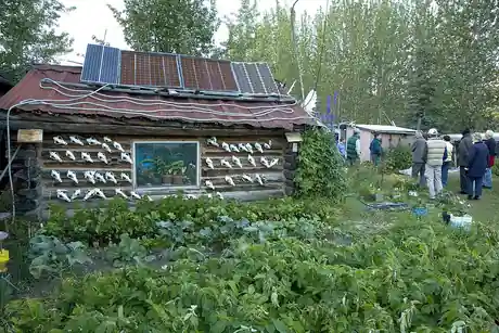
Featured photo: Remote off-grid log cabin powered by a rooftop solar photovoltaic array. Photo by Jon Sullivan on Public-domain-image.com via Wikimedia Commons (Public domain).
An off-grid cabin solar system requires more than simply adding up nameplate appliance wattages. Sizing a dependable setup balances daily kilowatt-hour consumption, inductive motor-starting surges from water pumps, sufficient battery autonomy for cloudy weather, and your site’s actual winter solar resource rather than an optimistic annual average.
⚡ Quick Answer: Typical Off-Grid Cabin Sizing Baseline
For a typical three-season cabin running an efficient refrigerator, LED lighting, internet equipment, a microwave, and a small domestic water pump, a practical starting baseline is approximately 2 to 3 kW of solar PV, 8 to 12 kWh of usable battery storage (typically LiFePO4), and a 3,000 W to 5,000 W pure-sine wave inverter. A deep-well pump, electric cooking, heavy winter snow cover, or year-round occupancy will require substantially more capacity, along with an integrated backup generator.
⚠️ Important Engineering & Sizing Warning
Do not size a system from this example alone. Your final design depends on exact site coordinates, winter solar insolation, pump nameplate data (including Locked Rotor Amperage), wiring distances, ambient battery temperatures, locally adopted electrical codes, and which loads must run simultaneously. This guide walks through the engineering sizing process for preliminary planning; it does not replace a site-specific electrical design, manufacturer documentation, permits, or professional inspection.
📖 Guide Contents & Quick Navigation
- 1. Start with the Cabin Use Case
- 2. Sizing an Off-Grid Cabin Solar System: The Load List
- 3. Calculate Daily Energy (Wh/kWh)
- 4. Size the Battery Storage Bank
- 5. Size the Solar PV Array
- 6. Size Inverter & Water Pumps
- 7. Choose System Voltage: 12V/24V/48V
- 8. Cold-Weather Battery Protection
- 9. Plan Backup Generator Integration
- 10. Panel Racking & Wooded Siting
- 11. Planning-Level Cost Expectations
- 12. Cabin Winterization Protocol
- 13. Safety & Electrical Code Checklist
- 14. Frequently Asked Questions
- 15. References & Technical Sources
1. Start with the Cabin Use Case
In renewable system engineering, treating a remote cabin like a “small suburban house” or an “oversized camper van” is a frequent cause of unexpected winter shutoffs. Designing a reliable off-grid cabin solar system requires matching equipment to distinct physical operating conditions:
- Weekend Outposts: Unoccupied for 10 to 20 consecutive days, followed by sudden Friday-to-Sunday energy demand. Systems must be engineered to prevent phantom idle drain from exhausting batteries during unattended weeks.
- Three-Season Family Retreats: Active from spring through late autumn. These cabins run full refrigeration, water pumps, lighting, and entertainment, but are shut down and winterized before sub-zero winter freezes begin.
- Year-Round Homesteads: Continuously occupied through midwinter. Because winter solar generation can drop by 60% to 80% compared to summer, these systems require steep winter array tilts, generator auto-charging, and heated battery enclosures.
- Unattended Winter Cabins: Cabins left vacant through winter but requiring continuous low-draw freeze alarms, security sensors, or cellular telemetry. These require strict isolation of high-draw AC inverters to avoid battery starvation.
💧 The Cistern Analogy: Understanding Asymmetric Cabin Energy
Think of a remote cabin battery bank as a mountain rainwater cistern. In a permanent residence, water is consumed and replenished continuously every day. At a weekend cabin, nobody draws power for three consecutive weeks, yet continuous phantom loads—inverter idle consumption, telemetry modems, and security sensors—silently siphon stored energy hour after hour. If snow blankets the solar panels for 10 days, this steady baseline drain empties the battery bank. When you arrive on Friday evening in freezing weather and start heavy appliances, the battery management system (BMS) abruptly disconnects on low voltage.
2. Sizing an Off-Grid Cabin Solar System: The Load List
Every dependable sizing calculation starts with separating electrical consumption into two independent engineering metrics: Total Daily Energy (Watt-hours / kWh), which dictates battery capacity and solar array size, and Peak Inverter Power (Watts), which dictates inverter capacity and conductor sizing.
When compiling your load worksheet, list running wattage, starting surge, daily operating hours, and whether the appliance operates during occupied weekends or stays active during vacant periods:
| Appliance / Load | Voltage & Type | Running Watts | Starting Surge / LRA | Daily Hours | Daily Energy (Wh) | Operating Mode | Engineering Design Notes |
|---|---|---|---|---|---|---|---|
| Efficient AC Fridge (10–12 cu ft Energy Star) | 120V AC | 40 W – 60 W | 300 W – 500 W | 8 – 10 hrs (duty cycle) | 320 – 500 Wh | Occupied Only | Modern variable-speed compressor avoids large surge. Measured plug-in energy meter data is preferable to multiplying running watts by hours. Emptied & door ajar when winterized. |
| 1/2 HP Deep-Well Submersible Pump (240V) | 240V AC (Split-Phase) | 850 W – 1,000 W | Nameplate LRA (e.g. 25–35A LRA) | 0.5 – 0.8 hr | 425 – 800 Wh | Occupied Only | Requires 120/240V split-phase inverter output. High starting inrush; check soft-starter or VFD compatibility with manufacturer (e.g., Franklin Electric AIM Manual). Breaker locked out when vacant. |
| Starlink Standard (Gen 2 / Gen 3) | 120V AC | 75 W – 100 W | 110 W (boot peak) | 12 – 16 hrs | 900 – 1,600 Wh | Occupied (Timer when away) | Manufacturer data: 50W–75W idle, 75W–100W active; snow-melt mode ramps to 100W–140W+. Disable automated snow-melt when unattended to prevent rapid battery depletion. |
| Starlink Mini (Native DC Dish) | 12V / 24V DC | 20 W – 40 W | 45 W | 12 – 24 hrs | 240 – 960 Wh | Occupied (Scheduled 1 hr/day when away) | Native DC operation bypasses AC inverter idle consumption. Ideal for intermittent remote communication. |
| Low-Power LTE Cellular Gateway / Modem | 12V / 24V DC | 5 W – 10 W | 15 W | 24 hrs | 120 – 240 Wh | Vacant Continuous | Runs continuously on native DC to transmit temperature, freeze alerts, and battery state without leaving AC inverter energized. |
| LED Cabin Lighting (6–10 fixtures) | 120V AC or 12V/24V DC | 30 W – 60 W | 60 W | 4 – 5 hrs | 120 – 240 Wh | Occupied Only | Low consumption (e.g., 30W × 4h = 120Wh; 60W × 4h = 240Wh). Using native 12V/24V DC lighting loops avoids inverter idle overhead during brief lighting needs. |
| Microwave / Drip Coffee Maker | 120V AC | 1,100 W – 1,400 W | 1,400 W (brief transformer inrush) | 0.25 hr (15 mins) | 275 – 350 Wh | Occupied Only | Microwave magnetron has brief inrush (~2× for ~0.5 s); coffee maker is purely resistive. Both dictate continuous inverter power rating, not daily battery kWh storage. |
| Inverter Idle Standby Loss (Tare Draw) | Internal AC circuit | 25 W – 50 W | 50 W | 24 hrs | 600 – 1,200 Wh | Occupied Only (Switched OFF when away) | Continuous internal transformer and circuit standby loss. Must be switched completely OFF or placed in search mode during vacant winter periods. |
3. Calculate Daily Energy (Wh/kWh)
Summing the occupied load profile in our worksheet gives an average daily energy budget of approximately 3,500 Watt-hours (3.5 kWh) per occupied day. For an off-grid cabin solar system, daily energy budgeting must account for two distinct operating modes that are sized independently:
- Occupied Mode (Active Cabin): 3,500 Wh/day supporting food refrigeration, water pumping, domestic lighting, microwave cooking, satellite internet, and full AC distribution.
- Vacant Mode (Unattended Winter Standby): If the main inverter is left running, idle tare loss alone drains 600 to 1,200 Wh/day, risking battery depletion during 10-day winter snowstorms. By de-energizing the main inverter and powering only a native DC cellular modem (8 W × 24 h = 192 Wh/day), the cabin’s daily standby drain drops to under 200 Wh/day, easily maintained by a trickle charge even under heavy snow cover.
4. Size the Battery Storage Bank
In an off-grid cabin solar system, the battery bank must store enough usable kilowatt-hours to sustain essential loads through multi-day periods of heavy cloud cover or storms without replenishment. This buffer is called days of autonomy.
For most seasonal and weekend cabins, two days of autonomy (48 hours) is an economical planning target if paired with a backup generator. To convert daily watt-hours into nominal battery capacity, factor in your battery’s recommended depth of discharge and inverter conversion efficiency:
Where LiFePO4 depth of discharge is typically recommended at 80% (0.80) to maximize cycle life, and high-quality pure sine wave inverter efficiency is approximately 90% to 94% (0.92 average).
================================================================================
WORKED BATTERY SIZING EXAMPLE (3,500 Wh/Day, 2 Days Autonomy)
================================================================================
Daily Occupied Consumption:         3,500 Wh (3.5 kWh)
Desired Autonomy Target:             2 Days (7,000 Wh deliverable to loads)
Max Usable Depth of Discharge (DoD): 80% (0.80)
Inverter DC-to-AC Efficiency:        92% (0.92)

Nominal Capacity = (3,500 Wh × 2) ÷ (0.80 × 0.92)
                 = 7,000 Wh ÷ 0.736
                 ≈ 9,510 Watt-hours (9.51 kWh)

Practical Hardware Selection:
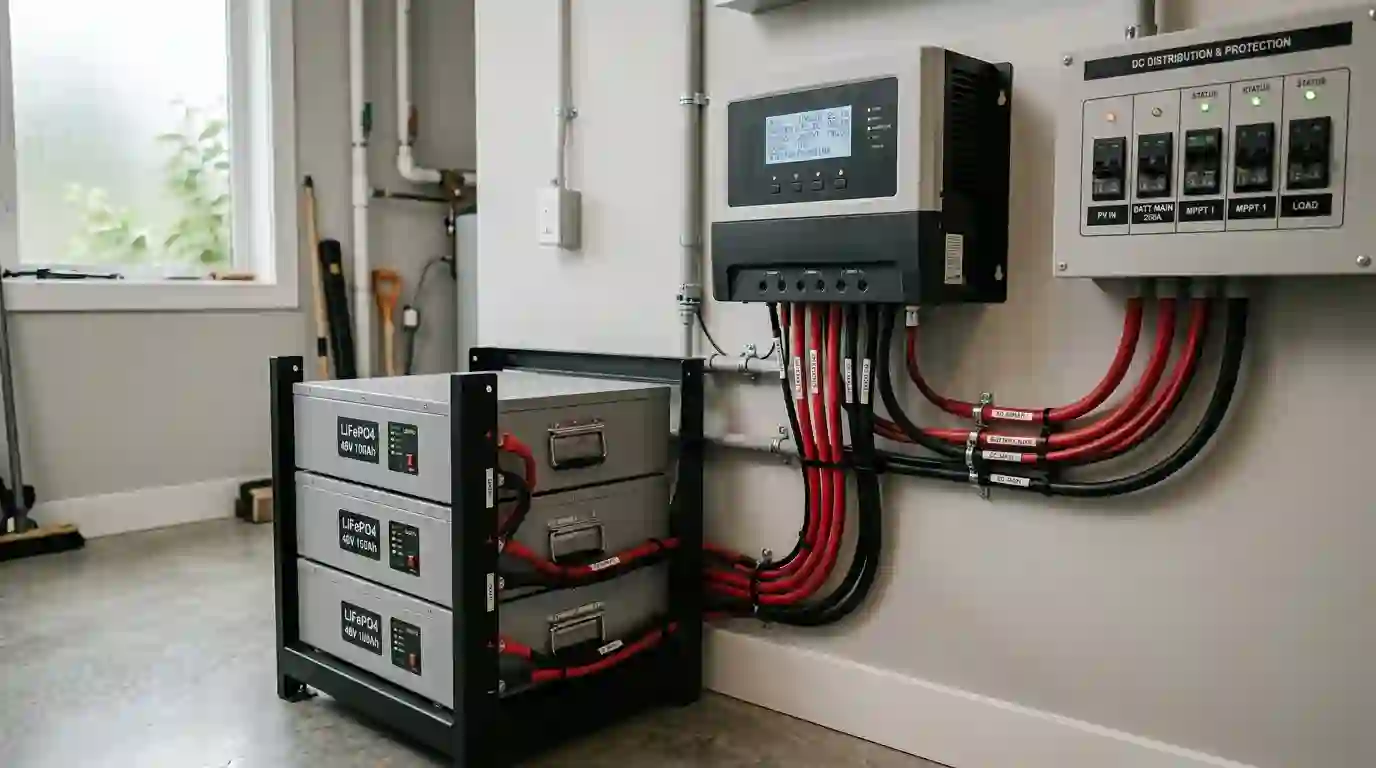
Two 48V 100Ah LiFePO4 server-rack modules:
2 × (51.2V × 100Ah) = 10,240 Wh (10.24 kWh nominal capacity)
Usable Energy Available (at 80% DoD): 10,240 × 0.80 × 0.92 = 7,536 Wh (2.15 Days Autonomy)
================================================================================
Planning Note: Substitute your own measured daily kilowatt-hours into this formula. In real installations, battery temperature, aging headroom, reserve margin policy, and manufacturer discharge ratings must be checked before purchasing.
5. Size the Solar PV Array
In an off-grid cabin solar system, the PV array must generate enough energy during the shortest days of your operating season to satisfy daily consumption and recharge depleted batteries. Because solar irradiance varies dramatically by latitude and season, sizing an array using a single generic “national average” sun-hour number leads to chronic winter undercharging.
To obtain reliable location-specific data, input your cabin’s exact geographical coordinates into NREL PVWatts (or the European Commission PVGIS database in Europe). Inspect the monthly solar insolation estimates—specifically December and January for year-round cabins, or October/April for three-season cabins.
System derate factor (typically 0.75) accounts for real-world environmental losses: dust, wiring voltage drop, MPPT charge controller conversion efficiency, and high-temperature thermal derating.
================================================================================
WORKED SOLAR ARRAY SIZING EXAMPLE (3,500 Wh/Day Baseline)
================================================================================
Daily Energy Consumption:           3,500 Wh (3.5 kWh)
Site Winter Solar Resource (PSH):    2.0 Peak Sun Hours (modeled for steep winter tilt)
System Derate Factor:               0.75 (25% total balance-of-system losses)

Required Array Wattage = 3,500 Wh ÷ (2.0 PSH × 0.75)
                       = 3,500 ÷ 1.5
                       ≈ 2,333 Watts (2.33 kW DC)

Hardware Selection:
Six 400-Watt Tier-1 Monocrystalline Panels:
6 × 400 W = 2,400 Watts DC array rating.
Estimated Daily Midwinter Production = 2,400 W × 2.0 PSH × 0.75 = 3,600 Wh/day
================================================================================
Understanding Tool Limitations: Tools like PVWatts provide valuable irradiance models, but they are production-estimation tools—they do not model battery state-of-charge limits, generator dispatch schedules, extended snow burial, or three consecutive days of zero-production blizzards. For remote cabins, array sizing must always be paired with realistic storage and backup policies.
6. Size Inverter & Water Pumps
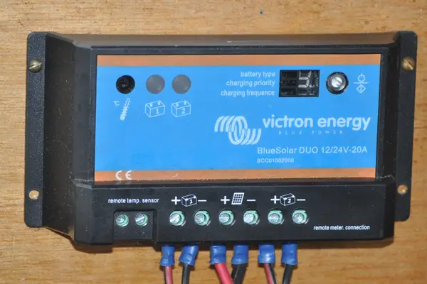
While battery storage dictates how long an off-grid cabin solar system can operate without sun, the inverter dictates what you can turn on at the exact same moment. An inverter must be sized to handle continuous simultaneous running loads plus the severe inrush surge of electric motors.
Continuous Power Sizing
Sum the wattages of all appliances that might run together during a typical evening (e.g., refrigerator 60W + Starlink 90W + lights 60W + television 80W + microwave 1,200W + water pump 900W = 2,390 W). Multiply by a 1.25 (25%) safety headroom factor to keep the inverter operating within its continuous thermal comfort zone: 2,390 W × 1.25 = 2,988 W. A 3,000 W to 4,000 W inverter satisfies this continuous demand.
Motor Starting Surges & Deep-Well Pumps
Motor-driven loads—specifically 240V deep-well submersible pumps, air compressors, and refrigeration compressors—demand a substantial starting surge (Locked Rotor Amperage or LRA) lasting 0.5 to 1.5 seconds during initial motor acceleration. Motor-starting current can be several times running current, but the correct design figure is the pump’s nameplate LRA specification, not a generic rule of thumb.
Pump horsepower alone is insufficient for sizing. Your design depends on:
- Operating Voltage (120V vs 240V split-phase requirement).
- Motor phase (single-phase vs three-phase).
- Full-load running current and nameplate Locked Rotor Amperage (LRA).
- Two-wire vs three-wire motor construction (three-wire motors utilize external control boxes).
- Pump-controller compatibility (soft-starter or variable-frequency drive).
- Down-hole wire gauge and one-way cable voltage drop.
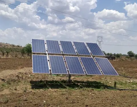
For single-phase 3-wire submersible pumps, two proven technologies reduce starting stress on off-grid inverters:
- Electronic Soft-Starters: Progressively ramp starting voltage, typically reducing starting inrush current by 40% to 60%.
- Variable-Frequency Drive (VFD) Pump Controllers: Controllers such as the Franklin Electric SubDrive or MonoDrive provide constant water pressure, eliminate starting inrush spikes entirely through controlled frequency ramping, and operate smoothly from off-grid inverters and generators. Always confirm compatibility with the pump manufacturer via resources like the Franklin Electric AIM Application Manual.
7. Choose System Voltage: 12V, 24V, or 48V
Choosing the system voltage for an off-grid cabin solar system (12 V, 24 V, or 48 V nominal DC architecture) is driven primarily by current (amperage), wire run distances, inverter power, and balance-of-system safety:
- 12 Volts DC: Suitable only for small weekend camps with continuous inverter capacity under 1,000 W to 1,200 W and native 12V DC loads. Delivering 3,000 W at 12 V requires over 250 Amperes, demanding impractically heavy conductors (4/0 AWG) and generating excessive resistive heat loss.
- 24 Volts DC: A practical choice for intermediate cabins with inverter capacity between 1,200 W and 2,500 W, cutting current in half compared to 12 V.
- 48 Volts DC: The established industry standard for cabins requiring more than 2,500 W of continuous power, 240V deep-well pumps, or split-phase distribution. At 48 V, delivering 3,000 W requires only ~62.5 Amperes, permitting standard cable gauges, minimizing voltage drop over long runs, and enabling direct compatibility with modular 5.12 kWh server-rack LiFePO4 batteries.
8. Cold-Weather Battery Protection
Unlike suburban residential batteries installed in conditioned basements, cabin batteries often endure sub-zero mountain freezes. Understanding thermal boundaries is critical to preventing permanent battery failure:
- Discharge Temperature Limits: Quality LiFePO4 batteries can safely discharge at temperatures down to -20°C (-4°F), though internal resistance increases and delivered capacity temporarily drops by 15% to 30%.
- Charge Temperature Lockout: Many LiFePO4 batteries strictly prohibit charging below 0°C (32°F) because low-temperature charging causes irreversible metallic lithium plating on anodes, degrading cell capacity and creating internal short-circuit hazards. Follow the exact charging-temperature limits published for your battery model.
- Cell Internal vs. Ambient Enclosure Temperature: Cold outdoor air does not instantly chill battery cores, but once cold-soaked, cells must not receive charge current until heated.
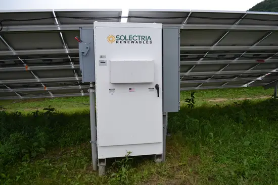
For unheated winter cabins, implement one of three thermal protection strategies:
- Internal Self-Heating Batteries: Modules with integrated thermal elements that divert incoming solar charging current to warm internal heating pads to 5°C (41°F) before enabling charge flow to the cells.
- Insulated Thermal Enclosures: House the battery bank inside a sealed wooden box lined with 2 inches of R-10 to R-13 rigid polyisocyanurate foam, equipped with a low-wattage silicone heating pad controlled by a dual-stage digital thermostat.
- BMS Low-Temperature Cutout: Verify that your charge controller or Battery Management System (BMS) includes an active temperature probe that automatically disables charging when cell temperatures drop below 0°C (32°F).
9. Plan Backup Generator Integration
When designing an off-grid cabin solar system, attempting to achieve 100% solar independence through a 7-day midwinter blizzard requires massive overbuilding—purchasing four times as many solar panels and battery modules as you need from April through October. Sizing solar for 85% to 90% of your annual needs and bridging winter bottlenecks with an auxiliary generator is far more cost-effective.
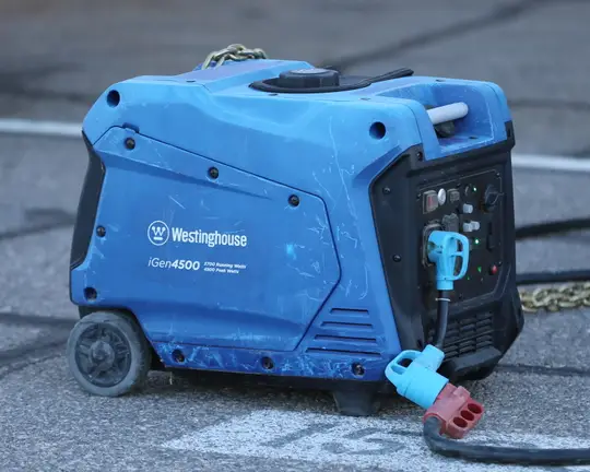
Key guidelines for integrating a backup generator into an off-grid cabin:
- Two-Wire Autostart Integration: Pair a generator equipped with electric start with an inverter-charger featuring programmable dry-contact relays. Set the autostart trigger to 20% to 25% State of Charge (or ~50.8V to 51.2V on a 48V bank).
- Efficient Bulk Charging: Rather than running a 4,000 W generator all day to power a 40 W light bulb, the inverter draws full charger capacity (e.g. 2,500 W to 3,500 W) to rapidly recharge the battery bank to 80% SoC in 2 to 3 hours, then automatically turns the engine off.
- Dual-Fuel Propane (LPG): Propane is cleaner than gasoline, does not degrade or gum up carburetors during 6 months of seasonal cabin vacancy, and ties into existing cabin propane tanks.
- Carbon Monoxide (CO) Safety: Always position generators outdoors at least 20 feet away from cabin windows, doors, and vents per CPSC and NFPA guidelines. Install certified, battery-backed carbon monoxide detectors inside all sleeping quarters.
10. Panel Racking & Wooded Siting
Most cabins are situated in wooded, mountainous environments surrounded by tall pines, oaks, and hillsides. This creates localized solar obstacles that suburban rooftops rarely encounter:
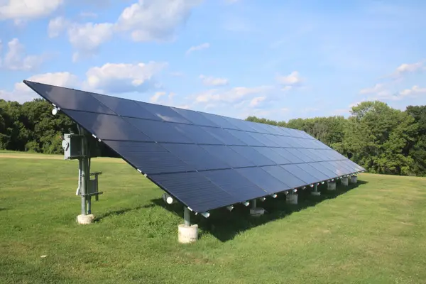
| Mounting Architecture | Shade Avoidance | Snow Shedding & Access | Installation & Trenching Scope |
|---|---|---|---|
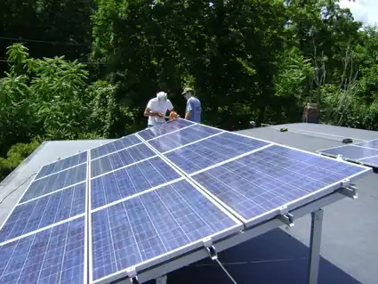
| Rooftop Racking | Constrained by cabin roof pitch and orientation; tall surrounding trees can cast afternoon shade across strings. | Steep metal roofs (8/12 to 12/12) shed snow, but ladder access for manual clearing or seasonal tilt adjustment is hazardous in icy conditions. | Cheapest upfront; short wire runs to power equipment; no ground excavation or concrete ballasts required. |
| Clearance Ground Mount | Superior; array can be sited 50 to 150 feet away in an open meadow clearing to maintain an unshaded solar window. | Panels can be set to steep seasonal winter angles (55°–65°) to promote natural snow shedding and cleared safely with a squeegee from the ground. | Requires underground conduit trenching below frost lines. Running panels in high-voltage series strings (150V–350V Voc) minimizes line voltage drop. |
| Top-of-Pole Mount | Excellent; elevates array 8 to 12 feet above ground brush, deep snow drifts, and wildlife contact. | High angle clears snow naturally above snowdrifts with zero manual shoveling required. | Requires deep augered holes with substantial concrete ballast to resist high wind shear loads. |
11. Planning-Level Cost Expectations
Component costs for an off-grid cabin solar system have stabilized significantly in 2026, driven by competitive LiFePO4 cell production and integrated all-in-one hybrid inverter-chargers. The table below presents planning-level budget estimates for the U.S. market (2026) for early project planning:
ℹ️ Planning Estimate Disclaimer
The ranges below reflect typical retail equipment pricing from reputable North American distributors. Turnkey figures include regional permitting, electrical inspection, balance-of-system safety hardware, trenching labor, and licensed installation. Real costs vary significantly by geographical region, site terrain, distance to utility access, and shipping freight. These figures are planning prompts, not binding contractor proposals.
| System Archetype | Core Equipment Included | DIY Equipment Only (USD) | Turnkey Professional Install (USD) |
|---|---|---|---|
| Tier 1: Weekend Outpost (0.8–1.2 kW Array) | 2–3× 400W panels, 2.5 kWh LiFePO4 (12V/24V), 1,200W Pure Sine Inverter, 60A MPPT, roof racking, DC disconnects. | $2,400 – $3,600 | $5,500 – $8,000 |
| Tier 2: 3-Season Family Cabin (2.4 kW Array) | 6× 400W panels, 10.2 kWh Heated LiFePO4 (48V), 3,500–4,000W Inverter-Charger, 80A MPPT, Ground Mount racking, Combiner box. | $5,800 – $8,200 | $11,000 – $16,500 |
| Tier 3: Year-Round Homestead (4.8 kW Array) | 12× 400W panels, 20.4 kWh Server-Rack LiFePO4, 6,000W–8,000W Split-Phase Inverter, Conduit trenching, 4.5kW Inverter Generator. | $11,500 – $16,000 | $22,000 – $32,000 |
12. Cabin Winterization Protocol
When closing an off-grid cabin solar system for late autumn and winter, following an orderly electrical shutdown procedure protects sensitive equipment from irreversible freeze damage and deep depletion:
- Drain and Isolate Potable Water Systems: Cut breaker power to the deep-well submersible pump or pressure pump before opening cabin drain valves. Never let a pressure pump dry-cycle if an automatic pressure switch activates while lines are empty.
- De-energize the Main AC Inverter: Switch the main inverter-charger power switch to the “OFF” position. This halts internal transformer idle power consumption (saving 25W–50W continuous tare loss).
- Maintain Solar Battery Float: Keep the DC solar charge controller and PV disconnect switch active. This allows the solar array to trickle-charge and maintain battery bank SoC over the winter months.
- Verify Low-Temperature Charging Protection: Ensure the charge controller temperature sensor is securely attached to the battery terminal or that the internal BMS thermal cutout is confirmed active at 32°F (0°C).
- Switch Off Non-Essential DC Phantom Loads: Unplug USB charging converters, 12V television adapters, and auxiliary communication gear unless required for freeze monitoring.
13. Safety & Electrical Code Checklist
An off-grid cabin solar system involves high-voltage DC arrays, massive short-circuit battery energies, and split-phase AC distribution. National Electrical Code (NEC) standards provide essential protection against shock and electrical fires:
📋 Code Scope & AHJ Adoption Notice
NEC Articles 690 (Solar Photovoltaic Systems), 706 (Energy Storage Systems), and 710 (Stand-Alone Systems) govern independent off-grid power systems in the United States. However, the legally enforced edition (e.g., NFPA 70-2023 vs. 2020 or 2017) and specific amendments depend on your local Authority Having Jurisdiction (AHJ). Have your final single-line diagram and installation reviewed by a qualified licensed electrician or local building authority.
- NEC Article 710.15(A) (Stand-Alone Capacity): In stand-alone off-grid systems, the power supply (inverter) is explicitly permitted to have less capacity than the total calculated premises load. However, the supply must be rated at least equal to the largest single utilization equipment load connected to the system (e.g., your deep-well pump motor starting surge).
- Overcurrent Protection & Interrupt Ratings (AIC): Because lithium battery banks possess near-zero internal resistance, they can deliver very high short-circuit currents during a terminal fault. Overcurrent protective devices must have an adequate Ampere Interrupting Capacity (AIC) per NEC 706.30 and manufacturer fault-current ratings. Always install an appropriately rated, listed Class-T DC fuse or heavy-duty DC breaker within close proximity of the battery terminal.
- DC Disconnect Switches: Install listed, accessible DC disconnect switches between the solar array and charge controller, and between the battery bank and inverter, to permit rapid isolation during emergency servicing.
- Equipment Grounding & Surge Protection: Bond all metal racking, equipment enclosures, and combiner boxes to a common grounding electrode system. Because remote cabins feature extended outdoor conductor runs through open terrain, install listed Type 1 or Type 2 DC Surge Protective Devices (SPDs) inside the PV combiner and on AC distribution panels.
14. Frequently Asked Questions
Can I run an air conditioner or electric heater in an off-grid cabin?
Air conditioning is highly feasible during summer months using high-efficiency inverter mini-split heat pumps (20+ SEER2) drawing 450W to 900W, which directly coincides with peak summer solar irradiance (5–6 Peak Sun Hours) on a 48V system. In contrast, electric space heating in winter is economically unfeasible: a standard 1,500W resistive space heater running for 8 hours consumes 12,000 Wh (12 kWh), demanding thousands of dollars in oversized battery capacity during the lowest solar generation window of the year. Remote cabins rely on high-efficiency wood stoves, pellet stoves, or direct-vent propane heaters for thermal warmth, reserving battery storage for lighting, refrigeration, pumps, and electronics.
How do I power a 240V deep-well pump from an off-grid cabin solar system?
To power a 240V deep-well pump without tripping inverters: (1) install a 48V split-phase inverter capable of native 120V/240V dual-leg output sized for locked-rotor amp (LRA) surges, and verify with the pump manufacturer whether an approved soft-starter can be added (applicable to 3-wire motors with external control boxes); (2) install an approved step-up autotransformer to balance a 120V inverter leg up to 240V split-phase; or (3) swap an older AC submersible for a high-efficiency solar-direct DC helical-rotor submersible pump installed directly within your existing well casing.
What happens if snow covers the cabin solar panels for two weeks while I am away?
If panels are blanketed in snow and solar production drops to zero, any active devices will draw exclusively from the battery bank. If you shut down the main inverter and isolate non-essential loads prior to departure, healthy LiFePO4 batteries have an exceptionally low monthly self-discharge rate (~1–2%) and will easily survive weeks of darkness. If an inverter or heater is left on, the battery will deplete until the internal Battery Management System (BMS) executes a low-voltage emergency disconnect.
Should I choose a 12V, 24V, or 48V off-grid cabin solar system?
A 12V system is suitable only for Tier 1 weekend outposts with continuous inverter capacity under 1,000W–1,200W and 12V native DC loads. For loads between 1,200W and 2,500W, a 24V system cuts conductor sizes. For any cabin with a deep-well pump, microwave, refrigeration, or continuous inverter capacity exceeding 2,500W, a 48V system is standard engineering practice to keep continuous DC currents under 100A, minimize resistive heat loss, and maximize inverter efficiency.
Can I install an off-grid cabin solar system inside an unheated outbuilding?
Yes, provided the electronics are protected from water infiltration and extreme moisture condensation. If using lithium batteries in an unheated outbuilding, you must install self-heating battery modules or house them in an insulated enclosure equipped with thermostat-controlled heating pads powered by solar. Inverters and MPPT charge controllers function reliably in cold weather but should be shielded from dust, rodents, and humidity.
Do off-grid cabins require electrical permits and inspections?
In most jurisdictions, yes. While some unincorporated remote counties have relaxed enforcement, electrical installations involving high DC voltages, battery storage systems, and AC distribution panels are governed by National Electrical Code (NEC) Article 690 (Solar PV Systems), Article 706 (Energy Storage Systems), and Article 710 (Stand-Alone Systems). Permitted installations require approved disconnects, overcurrent protection, proper equipment grounding, and compliance with local fire separation clearances.
📚 15. References & Technical Standards
- NFPA 70 / National Electrical Code (NFPA 70-2023): Article 300 (Wiring Methods), Article 690 (Solar Photovoltaic Systems), Article 706 (Energy Storage Systems), and Article 710 (Stand-Alone Systems). NFPA 70 Reference. Local jurisdictions may enforce the 2020 or earlier edition; confirm adopted code cycle with your local AHJ.
- National Renewable Energy Laboratory (NREL): PVWatts Solar Resource Calculator and National Solar Radiation Database (NSRDB). NREL PVWatts.
- Franklin Electric: Submersible Motors Application, Installation, Maintenance (AIM) Manual — Single-Phase Motor Control, LRA Specifications, and SubDrive / MonoDrive VFD Controller Compatibility. Franklin AIM Manual.
- SpaceX / Starlink: Starlink Standard (Gen 3) and Starlink Mini Power & Environmental Specifications (2024–2026).
- Underwriters Laboratories & Standards: UL 1973 (Batteries for Stationary Applications), UL 9540A, and ABYC Standard E-11 (AC & DC Electrical Systems on Boats).
- Consumer Product Safety Commission (CPSC): Carbon Monoxide Safety Guidelines and Portable Generator Placement Recommendations.
- OffGridSolarCalc Directory: Detailed methodologies and research bibliographies are compiled on our Verified Sources and Methodology pages.
Engineering Disclaimer: This guide provides educational system planning calculations and component comparisons. Off-grid electrical power systems involve lethal DC and AC voltages, arc-flash risks, and chemical storage hazards. Always verify local building codes, structural wind/snow load calculations, and consult a licensed master electrician or NABCEP-certified professional prior to commissioning.