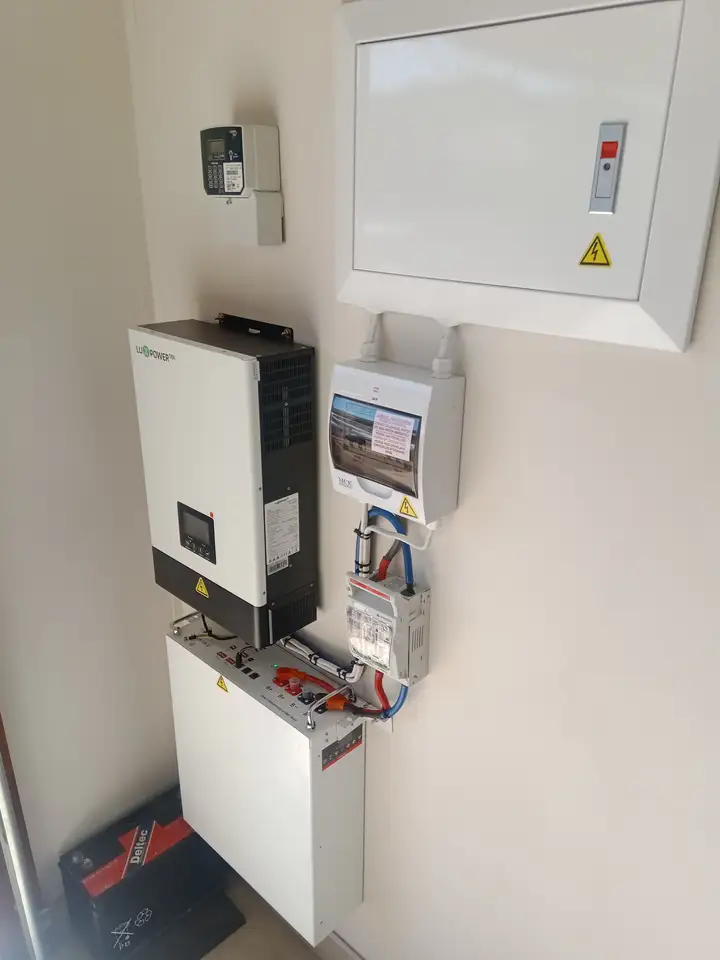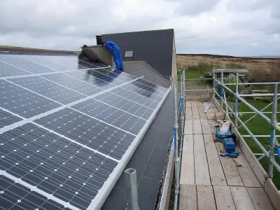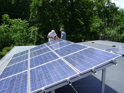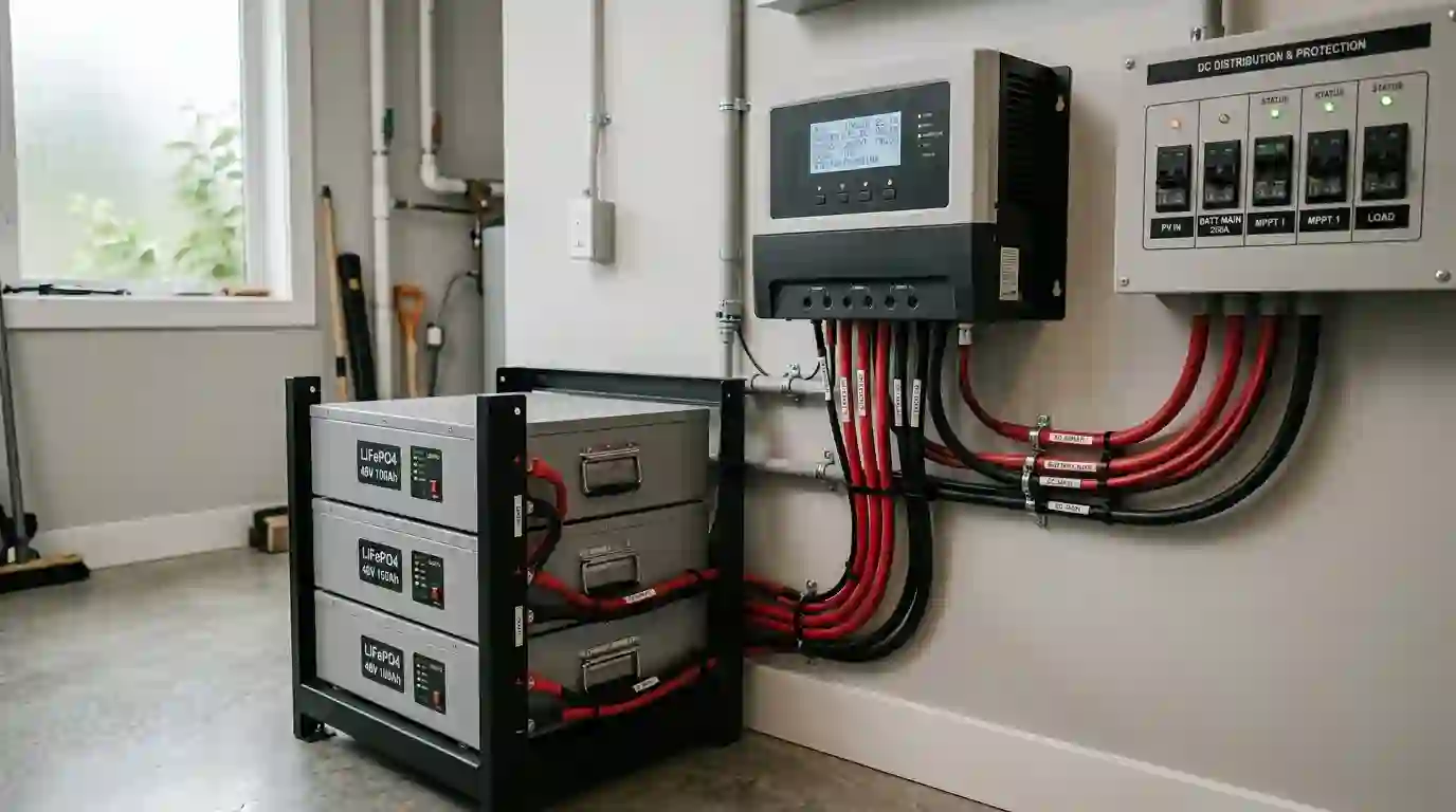
A charge controller regulates power from a photovoltaic (PV) array while charging a battery. Choosing a model is not determined by array watts alone: the controller must be compatible with the array voltage and current, the battery voltage and chemistry, and the manufacturer’s operating limits.
What a charge controller does
Solar modules produce DC power that varies with sunlight and temperature. A compatible controller converts or regulates that input for a battery and follows its configured charging profile. Available charging stages, temperature behavior, reverse-current protection, and supported battery settings vary by product. Check the manuals rather than assuming every controller uses the same behavior.
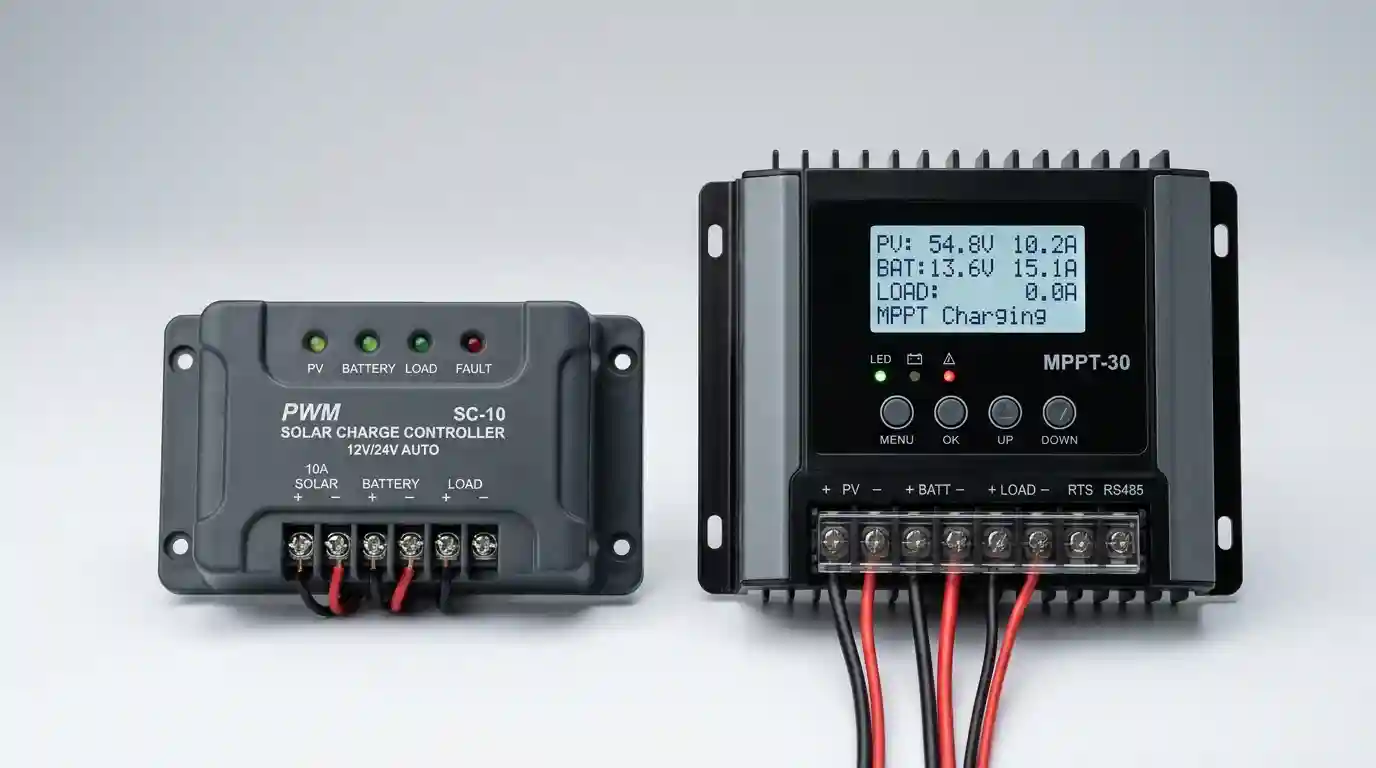
MPPT and PWM in brief
A PWM controller regulates a PV array that operates close to the battery charging voltage. An MPPT controller can operate the array at a different voltage and convert power to the battery-side voltage. Whether MPPT improves energy harvest, and by how much, depends on the module-array design, temperatures, shading, battery voltage, and controller. There is no fixed percentage gain that applies to every system.
Compare the exact product limits
Use the manufacturer’s current datasheet and manual for the exact controller model. Check each of these limits; a rating from a different model or brand is not a substitute.
- Battery-side charging current and power: Check the maximum output current and supported PV power at the battery-bank voltage you plan to use. Confirm that the battery manufacturer permits the resulting charging current.
- PV open-circuit voltage: Calculate the array’s cold-weather Voc using the module datasheet’s temperature coefficient, the expected minimum design temperature, and the manufacturer’s instructions. Compare the result with the controller’s maximum PV Voc. Do not rely on a universal percentage multiplier.
- PV current and operating range: Check the controller’s maximum PV short-circuit current, operating-voltage range, startup requirements, and any per-input or string limits. Follow the product’s stated rules for parallel strings.
- Array power and over-paneling: Check the allowed PV array power for the selected battery voltage and whether the manufacturer permits any input-power oversizing. Current limiting or power clipping is model-specific; do not assume excess input is always harmless.
- Battery compatibility: Confirm supported nominal battery voltages, chemistry, charge-voltage settings, temperature restrictions, and communication requirements. For lithium batteries, use settings approved for the exact battery and its BMS.
Use current as a first-pass estimate, not a model selection
For an idealized power conversion, battery-side current is approximately output power divided by charging voltage. For example, 800 W delivered at an assumed 28.8 V is about 27.8 A before conversion losses or any controller limit. This arithmetic is not a recommendation for a 28.8 V charge setting or a 30 A controller: actual charging voltage and allowable current depend on the battery, while the controller datasheet sets its power and output-current limits.
Array nameplate watts, battery nominal voltage, and a generic margin do not by themselves establish a controller rating. Verify the exact array and battery operating conditions against the product specifications and applicable requirements for the installation.
Calculate cold-weather array Voc from module data
For modules connected in series, their open-circuit voltages add. Module Voc generally rises as cell temperature falls, so the array’s cold-weather value must be checked against the controller’s maximum input voltage.
If the module datasheet gives a relative Voc temperature coefficient, a first-order estimate is: Voc at temperature T = module Voc at STC × [1 + coefficient per °C × (T – 25 °C)]. Apply the coefficient with its stated sign and units, use the site’s applicable minimum design temperature, then account for the number of modules in series. Follow the module and controller manufacturers’ calculation instructions and applicable local rules. Do not substitute a generic 10%, 15%, or 25% cold-weather factor.

Worked arithmetic example: an 800 W array
Suppose an illustrative array has four modules with a combined nameplate rating of 800 W and is paired with a battery system described as 24 V nominal. Those two figures are not enough to select a controller. The battery’s charging voltage is not its nominal voltage, and the module Voc, Voc temperature coefficient, Isc, series/parallel arrangement, and site design temperature have not been specified here.
As a separate arithmetic illustration only, 800 W divided by an assumed 28.8 V charging voltage is 27.8 A before losses. A real selection still needs the specific controller’s allowed PV power and current at that battery voltage, its maximum cold-corrected PV Voc, and the battery’s permitted charging current and settings. No controller model is declared suitable by this example.

Common selection errors to avoid
- Dividing array watts by nominal battery voltage and treating the result as a guaranteed controller rating.
- Applying a universal 25% controller margin or claiming that a general code rule supplies that formula.
- Using a generic MPPT efficiency, PWM loss, or annual energy-gain percentage as though it applied to every array.
- Estimating cold-weather Voc with a fixed multiplier instead of the module datasheet coefficient and the site’s design temperature.
- Assuming every controller clips excess array current or power safely, or that voltage is the only PV-side limit.
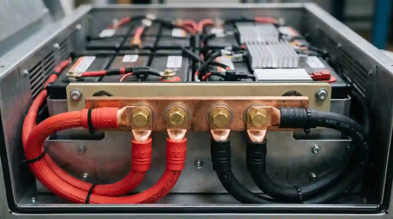
- Choosing cable sizes, fuses, busbars, or parallel-controller arrangements from a generic example. Those decisions require product instructions and installation-specific electrical requirements.
- Using a battery charge profile based only on chemistry labels instead of the exact battery manufacturer’s limits and BMS requirements.
What the site calculator provides
The off-grid system calculator provides preliminary estimates from entered assumptions and stored location data. Its displayed controller current is a heuristic based on estimated array size and assumed system voltage; it does not verify module Voc or Isc, cold-weather correction, a specific controller’s voltage or power limits, or battery charge settings. Treat that field as an unverified planning placeholder, not an equipment recommendation. The calculator also does not provide an installation design or code determination.
Frequently Asked Questions
That can provide a rough current estimate only when the relevant charging voltage and conversion assumptions are stated. It does not select a controller. Check its model-specific PV voltage, current, power, and battery limits, along with the battery maker’s charging limits.
No universal 25% factor determines a controller’s output-current rating. Applicable electrical rules depend on the circuit and jurisdiction, while controller selection must follow the exact product documentation and system conditions.
No fixed gain applies to every system. The difference depends on the array’s operating voltage, battery voltage, temperature, shading, and controller. Compare the actual configuration and manufacturer data rather than relying on a universal percentage.
Use the exact module’s Voc and temperature coefficient, the applicable minimum design temperature, and the module and controller manufacturers’ instructions. Add series-module voltages and compare the corrected value with that controller’s maximum PV Voc. A generic multiplier is not a substitute.
Do not assume so. Permitted PV short-circuit current, array power, and any oversizing or clipping behavior vary by model and battery voltage. Check every relevant limit in the exact manual.
No. It displays a preliminary current heuristic and does not check module electrical limits, cold-weather Voc, a specific controller model, or battery charge settings. It is not equipment selection or an installation design.
Sources and further reading
- Morningstar, TriStar MPPT specifications. The product table lists model-specific charge ratings, maximum PV Voc, battery voltages, and maximum operating power; other products have different limits.
- Morningstar, Charge controller settings for LiFePO4 batteries. The manufacturer directs users to battery-specific settings and compatibility guidance.
Manufacturer specifications and local requirements can change. Check the current documentation for the exact components and jurisdiction before making equipment or installation decisions.