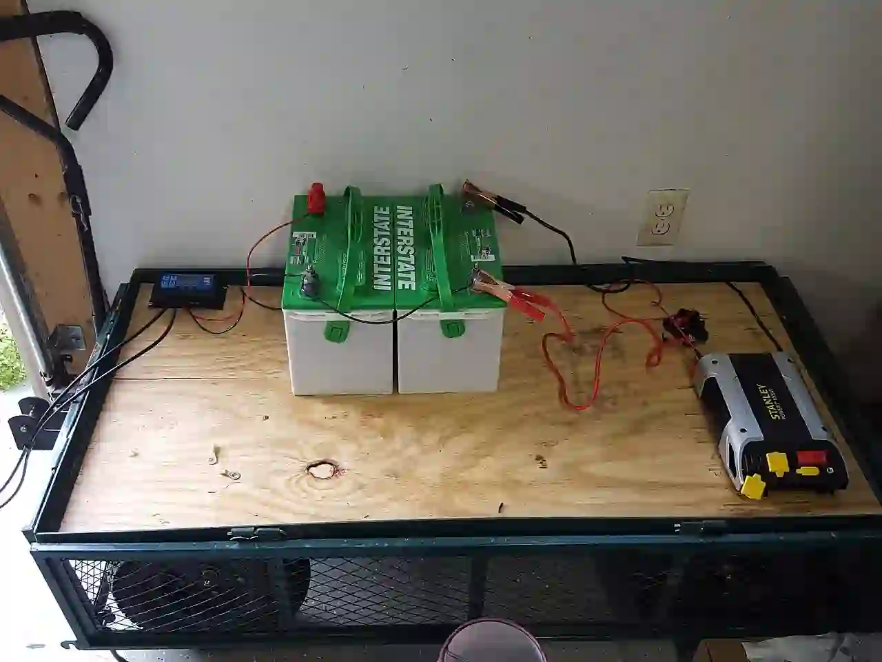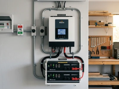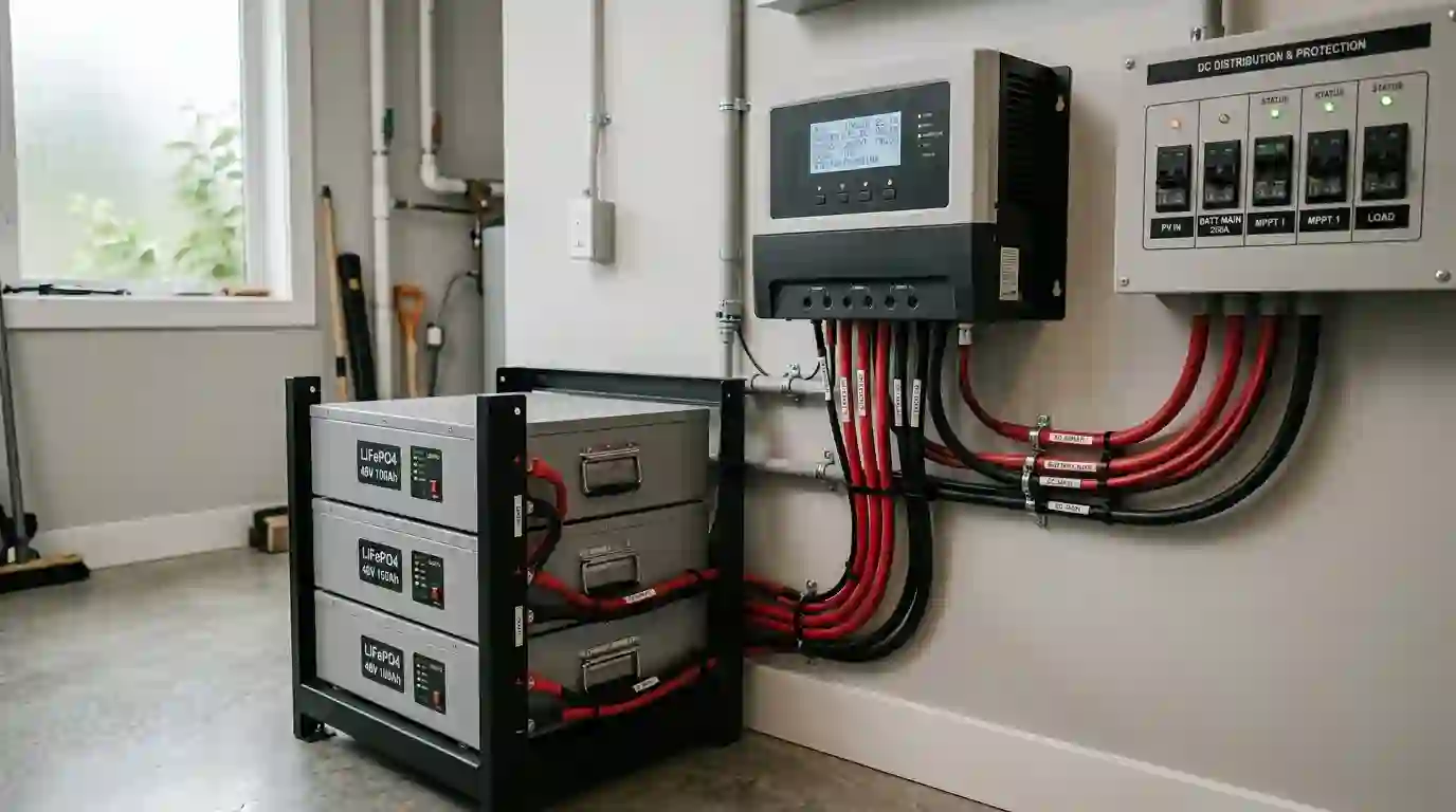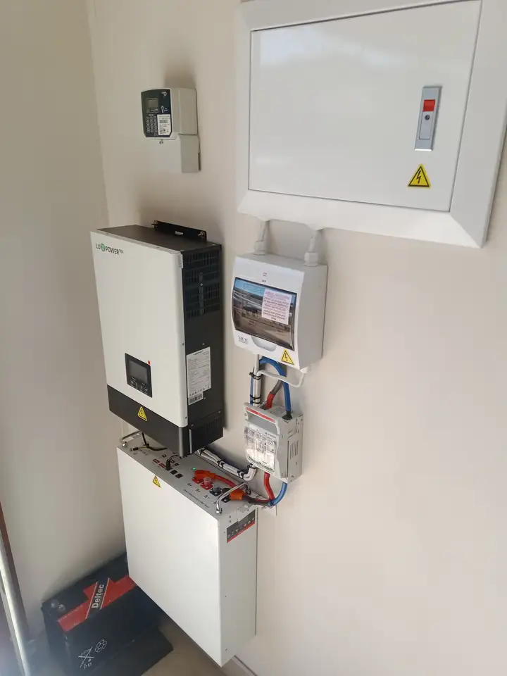
A battery bank combines storage units into a DC system. Series and parallel describe how nominal voltage and amp-hour capacity relate in simplified examples. Those labels do not by themselves show usable energy, compatibility, protection, or safe installation.
Series and parallel: nominal arithmetic
The examples below assume identical batteries with compatible specifications, and use only their nominal label values. They explain arithmetic; they are not connection instructions or approval to combine any specific products.
| Illustrative bank representation | Nominal voltage | Nominal capacity | Nominal stored energy |
|---|---|---|---|
| Two 12 V, 100 Ah units represented in series | 24 V | 100 Ah | 2,400 Wh (2.4 kWh) |
| Two 12 V, 100 Ah units represented in parallel | 12 V | 200 Ah | 2,400 Wh (2.4 kWh) |
| Four 12 V, 100 Ah units represented as two equal 24 V strings in parallel | 24 V | 200 Ah | 4,800 Wh (4.8 kWh) |
Nominal energy is voltage multiplied by amp-hours: Wh = V x Ah. For an arithmetic-only illustration, 80% of 4,800 Wh is 3,840 Wh. That percentage is an assumption, not a recommended depth of discharge or a promise of usable energy. Actual capacity depends on the battery model, operating conditions, reserve settings, discharge rate, temperature, and manufacturer limits.
System voltage and current
Battery, inverter, charger, and DC-load voltage ranges must be compatible with one another. A nominal voltage label is not the full operating range; actual voltage changes with product design, charge state, load, and charging conditions. Do not infer that equipment supports a voltage simply because it is commonly used in off-grid systems.
For a simplified power comparison, DC input current can be estimated as I = P / (V x efficiency). At an assumed 3,000 W load and 90% conversion efficiency, 3,000 W / (12 V x 0.90) is about 278 A, while 3,000 W / (48 V x 0.90) is about 69 A. The efficiency and nominal voltages are assumptions for this calculation only; actual input current depends on operating voltage, load, and the exact inverter. This arithmetic does not select a battery, conductor, fuse, disconnect, or busbar.
Battery compatibility and expansion
Do not decide that batteries can share a bank from chemistry, voltage, or amp-hour labels alone. Permitted series/parallel configurations and expansion rules vary by exact model and may depend on the internal battery-management system, firmware, age, operating limits, and other system components. Follow the manufacturers’ documentation for every unit in the proposed bank; do not assume that a generic configuration such as 4S4P is allowed.
Differences in model, capacity, condition, temperature, state of charge, internal resistance, and BMS behavior can affect current sharing and charging. Equal cable lengths alone do not guarantee equal current. If manufacturer documentation does not explicitly allow the proposed combination, treat compatibility as unverified.
Overcurrent protection, busbars, and disconnects
Battery fault current can be high, and protective-device selection is specific to the source, conductors, equipment, and installation. A fuse or breaker must have suitable DC voltage and interrupt ratings for the available fault current, and its current/time characteristics must coordinate with the protected conductors and equipment. A battery-management system or disconnect is not automatically a substitute for external protection. Class T is one fuse family, not a universal recommendation; this article does not choose a fuse class or rating.
Busbar, terminal, lug, and disconnect ratings and permitted arrangements are product-specific. The allowed number and orientation of lugs, terminal hardware, enclosure, torque, and isolation procedure must come from the exact equipment instructions and applicable requirements. Do not apply a generic torque value or assume that opening one switch makes every part of a battery system de-energized.
Conductors and grounding depend on the installation
There is no universal AWG size or maximum cable length for a given inverter wattage. Conductor selection depends on current, one-way route, voltage drop, conductor material and insulation, terminal ratings, ambient temperature, installation method, grouping, continuous-load rules, overcurrent protection, and local requirements. The former generic wire-size, ampacity, fuse, and cable-length tables are removed because their stated assumptions were not enough to approve those selections.
Grounding and bonding also depend on the inverter and charger design, AC arrangement, battery enclosure, system topology, and jurisdiction. A generic battery-bank diagram cannot determine the grounding method or conductor size for a particular property. Use the exact equipment documentation and the locally adopted electrical rules; do not infer a code-compliant design from the arithmetic in this article.
Operating limits and temperature
Charge and discharge temperature limits, voltage thresholds, permitted series/parallel count, current limits, and BMS behavior are model-specific. Use the exact battery documentation and approved system settings. The general terms lithium, LiFePO4, AGM, or lead-acid are not enough to determine compatible charge settings or a safe operating range.
Information needed for a real design
A project-specific review needs the exact battery, inverter, charger, protection-device, and conductor documentation, plus expected loads, voltage range, cable routes, environment, installation method, and jurisdiction. This article supplies none of the missing product or site information and does not replace that review.
Frequently asked questions
What changes in a series bank?
In the simplified model, nominal voltages add while amp-hour capacity remains that of one matched string. Whether a specific battery may be used in series is determined by its manufacturer.
What changes in a parallel bank?
In the simplified model, nominal voltage remains the same while amp-hour capacities add. Actual current sharing and permitted expansion depend on the exact batteries and system design.
Does equal cable length guarantee balanced current?
No. Similar cable lengths can reduce one source of resistance difference, but current sharing also depends on the full circuit, terminals, battery condition, and BMS behavior.
Which fuse class or rating should I use?
There is no universal answer in this article. The exact source fault current, DC voltage, conductors, equipment, and manufacturer and local requirements must be evaluated for the system.
Can I mix battery models or add a newer battery?
Do not assume compatibility based on matching voltage or amp-hour labels. Follow the exact manufacturers’ written expansion and configuration limits; otherwise compatibility is unverified.
Does a BMS remove the need for external protection?
Not automatically. Use only the protection architecture documented for the exact battery and system, with ratings and installation that meet applicable requirements.
References and product documentation
- U.S. Department of Energy, Homeowner’s Guide to Going Solar provides general solar-planning context; it is not a battery-bank wiring specification.
- NIST Energy Storage Safety Research provides broader research context, not product-specific installation approval.
- For actual limits and configuration, consult the current manuals and data sheets for the exact battery, inverter, charger, fuse, disconnect, busbar, and conductor, together with locally applicable electrical requirements.